Principle and calculation of quarter wavelength antennas
2022-03-14
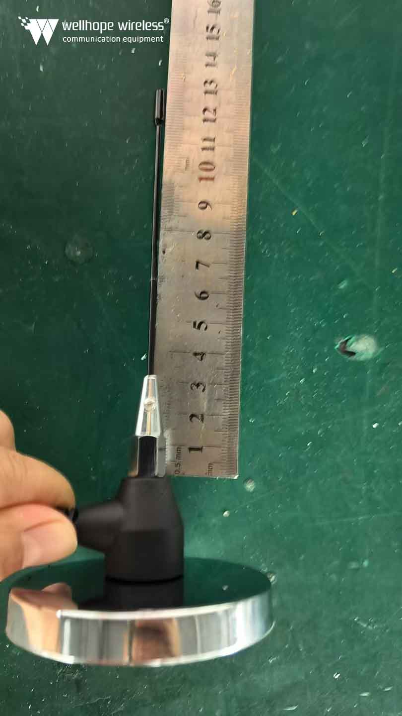
Principle and calculation of quarter wavelength antennas https://www.whwireless.com/ Estimated 5 minutes to finish reading Quarter wavelength antennas are more common in areas such as walkie-talkies, and their name is more technical than that of antennas that are distinguished by their shape. In this article, we will further discuss the characteristics of the quarter wavelength antenna by looking at the principles and applications of this antenna. First, the antenna's transmission principle Regarding the quarter wavelength antenna, we need to understand the basic principle of the antenna's emission first. Electricity travels through a conductor at a speed close to that of light, and when it encounters a discontinuity in the conductor, it is reflected back to the signal source. If the current is alternating and the reflected current returns to the origin or feed point at the right moment, then the current is reinforced by the subsequent cycles so that only a small amount of energy is required to maintain a standing wave within the antenna. That is, due to the presence of standing waves so that the antenna is in a resonant state. Thus transmitting electric waves into space. In the resonant state, the voltage in the current for the maximum of the midpoint (oscillator of the midpoint) is very little, but at both ends there is a great value, Ohm's law applies to the antenna, in the midpoint due to the current, the voltage is low, so the resistance is small, at both ends of the situation is exactly the opposite, thus the impedance is high. Second, the principle and application of quarter wavelength antenna According to the theory of transmission line, 1/4 wavelength open line is equivalent to a series resonant circuit, so its entire load is purely resistive, in some occasions, due to environmental factors, the length of the antenna is often limited, so there is a loaded antenna. According to the theory of transmission line, the length of the antenna is less than 1/4 wavelength multiples of its impedance is capacitive, when the antenna does not resonate, for this reason we can add an inductor on the antenna to balance with the antenna, so that the antenna resonance, we call this antenna for loading antenna. Theoretical and practical evidence, when the length of the antenna for the radio signal wavelength of 1/4, the antenna transmission and reception conversion efficiency is high. Compared to one-half wavelength, full wavelength, antenna size is much smaller, compared to the antenna transmitting and receiving efficiency and the highest ratio of antenna size, so commonly used quarter wavelength antenna. Third, how to calculate the quarter wavelength A quarter wavelength can be calculated by frequency, the formula is: the length of the antenna (in meters) = (300/f) * 0.25 * 0.96, f indicates the frequency in MHz, 0.96 is the wavelength shortening rate (electromagnetic wave propagation in the antenna, some factors lead to wavelength shortening...
View More

 News
News