Driving into the future - All-in-one antenna brings more reliable and efficient connectivity to Robotaxi
2024-03-13
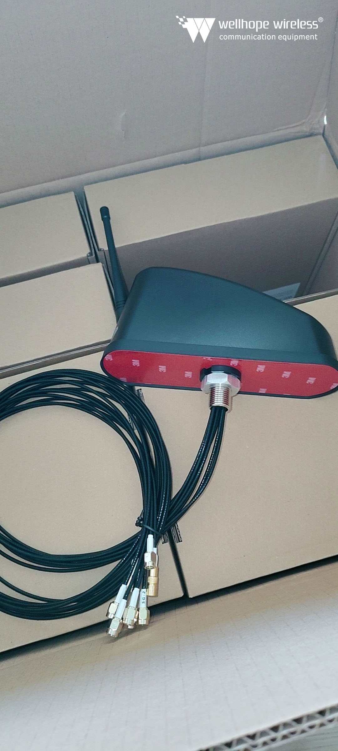
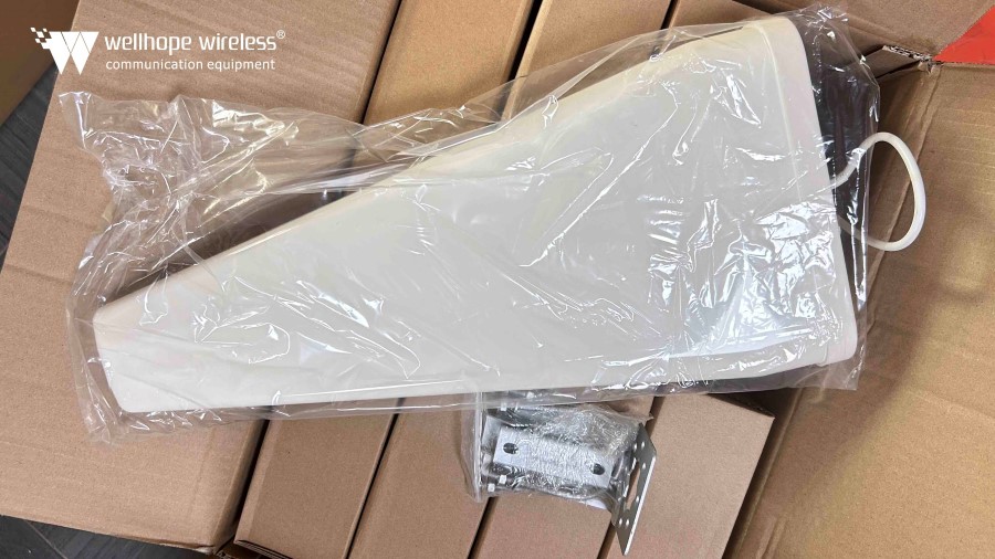
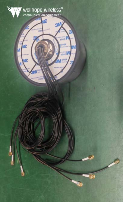
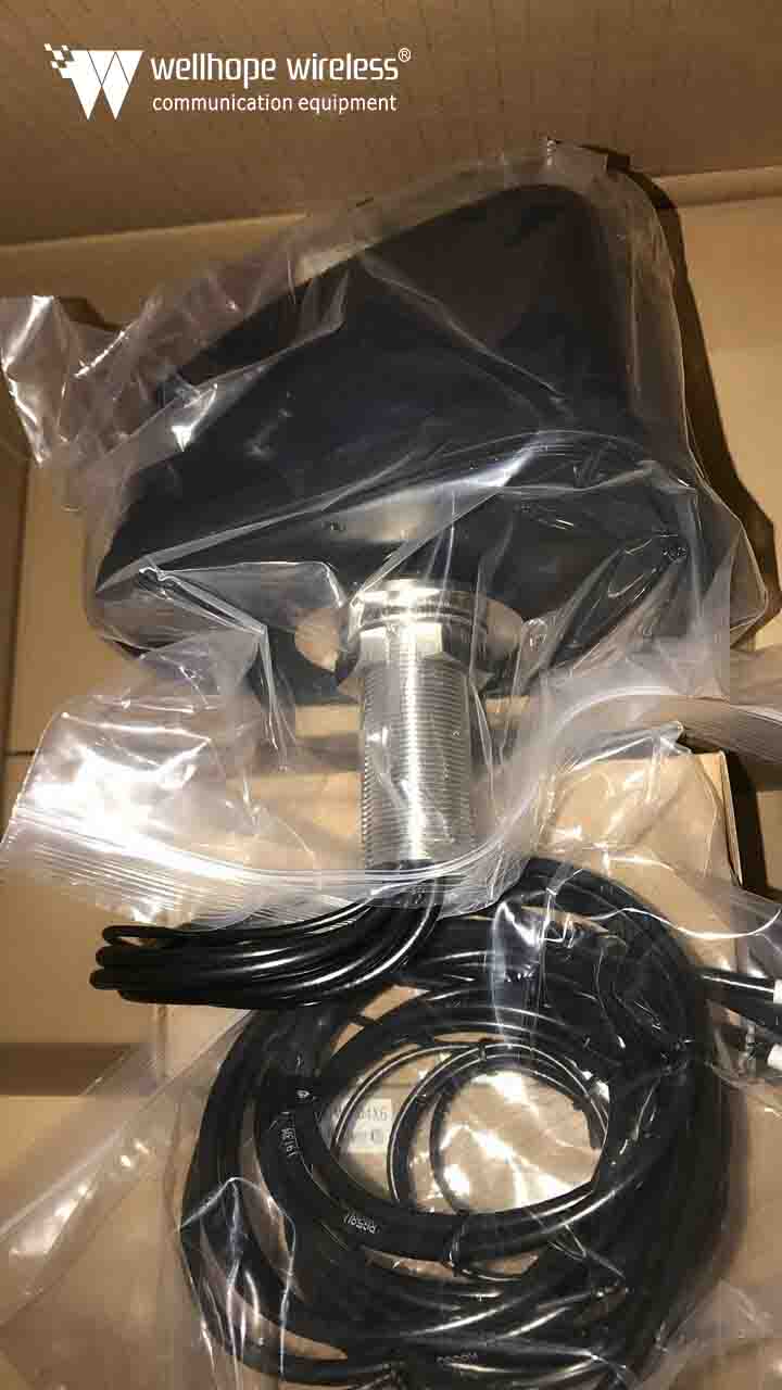
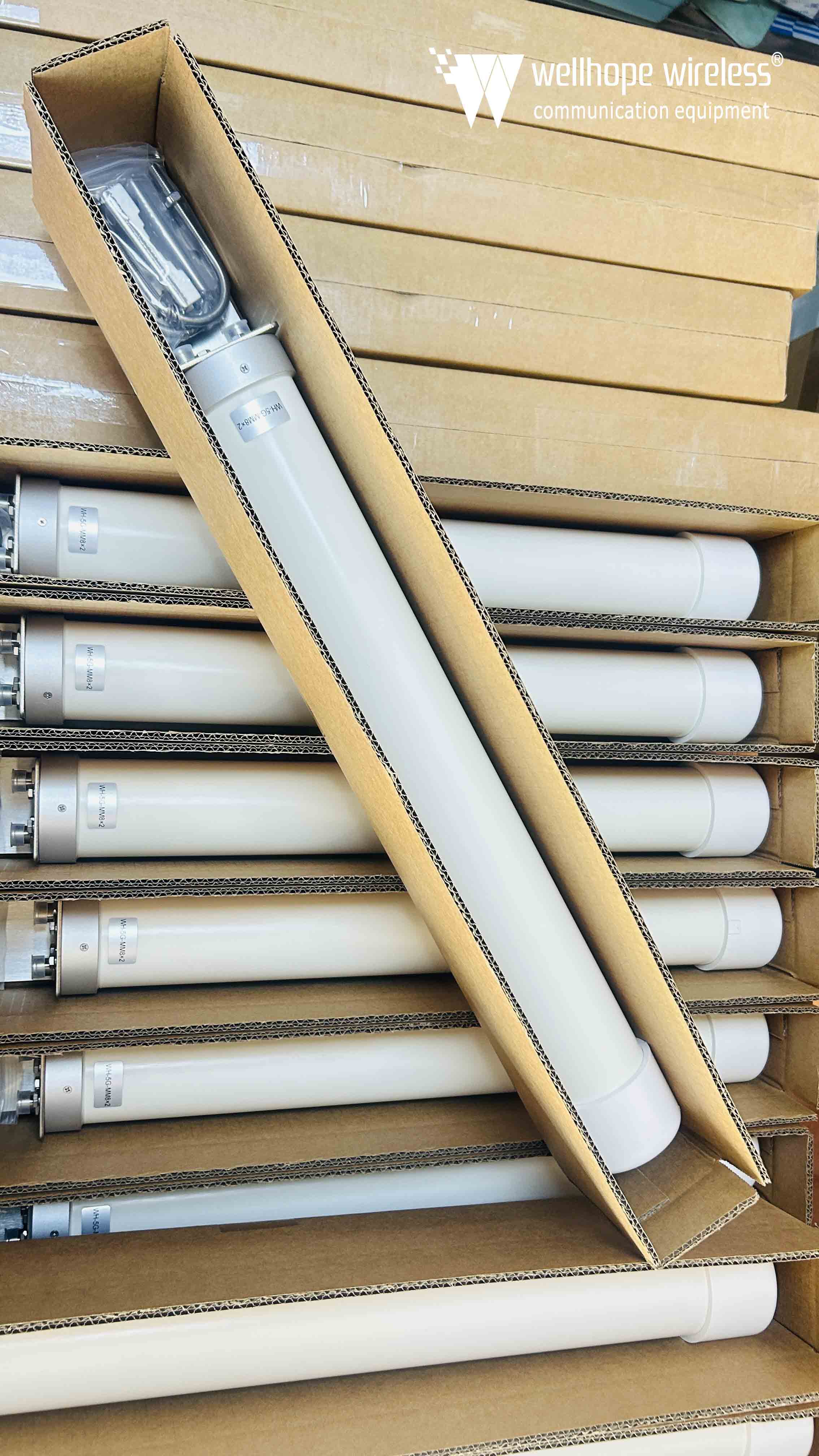
Driving into the future - All-in-one antenna brings more reliable and efficient connectivity to Robotaxi https://www.whwireless.com/ Estimated 15minutes to finish reading In today's world, autonomous driving technology is evolving and its applications are expanding rapidly, and Robotaxi (self-driving cabs) is one of the high-profile areas that are revolutionizing urban mobility. But to make Robotaxi feasible and safe, it must rely on a variety of advanced technologies. whwireless all-in-one vehicle antennas play a key role in ensuring the reliability and efficiency of communication, navigation and sensor applications. Background Robotaxi, or self-driving cabs, represent a revolutionary application of self-driving technology in urban mobility. They mark a major turning point in the future of mobility, freeing people from traditional cab services and enabling fully automated, efficient and environmentally friendly urban mobility solutions. Robotaxi refers to cabs equipped with self-driving technology that do not require a human driver to take control and instead rely on advanced sensors, artificial intelligence and computer vision systems to sense and navigate urban roads. Passengers can book a Robotaxi through a mobile app or other means and hail a vehicle when needed. Once the vehicle arrives, passengers can take a ride and the vehicle will then automatically and safely transport them to their destination. Pilot projects for the Robotaxi service have begun rolling out in Shanghai, Guangzhou, Shenzhen, Suzhou and Wuhan, working to commercialize the self-driving technology. These pilot projects have helped to validate the feasibility of the technology and gained valuable experience for future development. The introduction of Robotaxi will have a profound impact on urban transportation and mobility. They are expected to reduce traffic congestion, reduce traffic accidents, and improve the efficiency and sustainability of travel. At the same time, Robotaxi has the potential to improve urban air quality, reduce transportation emissions and make cities more livable. In addition, this technology can expand travel options, improve the efficiency of public transportation systems, and reduce reliance on personal vehicles. As an autonomous driving technology, Robotaxi's reliance on 5G, WiFi, and GNSS (Global Navigation Satellite System) is critical. 5G networks provide high-speed, low-latency communications that enable Robotaxi to exchange data in real time with central control systems, other vehicles, and infrastructure to ensure safe and efficient autonomous driving operations; WiFi connectivity expands communication options, enabling the vehicle to connect to local networks and cloud services to support real-time map updates, software upgrades, and vehicle diagnostics; and GNSS technology provides high-precision positioning and navigation information to help Robotaxi accurately determine its location, plan routes, and perform precise autonomous driving op...
View More

 News
News