Easy to understand! After reading it you are half an antenna expert
2023-11-04
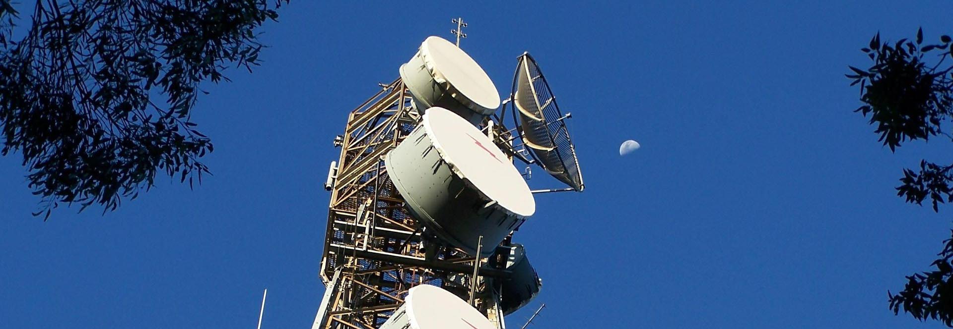
Easy to understand! After reading it you are half an antenna expert https://www.whwireless.com/ Estimated 20minutes to finish reading As we all know, antennas are used by base stations and cell phones to transmit signals. The word antenna in English is Antenna, which originally means tentacles. Tentacles are the two long thin wires on top of an insect's head. Don't underestimate such an inconspicuous thing, but it is the chemical signals sent by these tentacles that convey various social information. Similarly, in the human world, wireless communication also uses antennas to transmit information, but it is electromagnetic waves that carry useful information. The picture below is an example of a cell phone and a base station communicating with each other. If you raise your head to scrutinize the base station, you will find that at the top of the tower, there are some plate-like things, which is the protagonist of this article: communication antenna, the most often and cell phone direct eye contact is this goods. This antenna is called a directional antenna, as the name suggests, is that the signal emission is directed. If it is facing you, the signal just; if you stand behind it, then sorry, not in the service area! At present, the vast majority of base stations on the use of directional antennas, generally need three antennas to complete 360-degree coverage. To unveil the mysterious veil of this goods, it is necessary to dismantle it to see what is actually loaded inside. The internal empty, the structure is not complex well, is composed of vibrators, reflector plate, feed network and radome. These internal structures are doing what, how to realize the function of directional transmission and reception of signals? This is all from the electromagnetic wave to start. Peeling back the antenna's coat Antennas are capable of transmitting information at high speeds because they emit electromagnetic waves containing information into the air, traveling at the speed of light and eventually reaching the receiving antenna. It's like transporting passengers on a high-speed train. If you compare information to passengers, then the vehicle that carries the passengers: the high-speed train is the electromagnetic wave, and the antenna is the equivalent of the station, which manages the dispatching of the electromagnetic wave. So, what are electromagnetic waves? Scientists have studied the two mysterious forces of electricity and magnetism for hundreds of years, culminating in Maxwell of England's proposal that an electric current can produce an electric field in its vicinity, a changing electric field produces a magnetic field, and a changing magnetic field produces an electric field. Eventually this theory was confirmed by Hertz's experiments. With the electromagnetic field in such a periodic transformation, electromagnetic waves radiate and propagate into space. For more details, see the article, "Electromagnetic Waves Cannot Be Seen or Touched, This Young Man...
View More

 News
News