The reasons for the use of antenna covers and classification details
2022-01-21
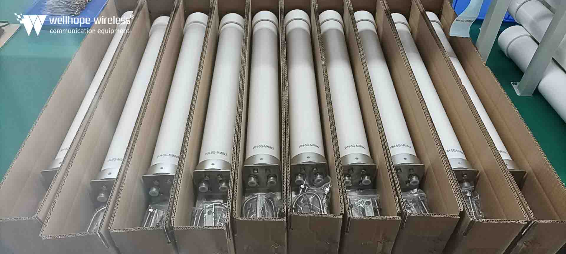
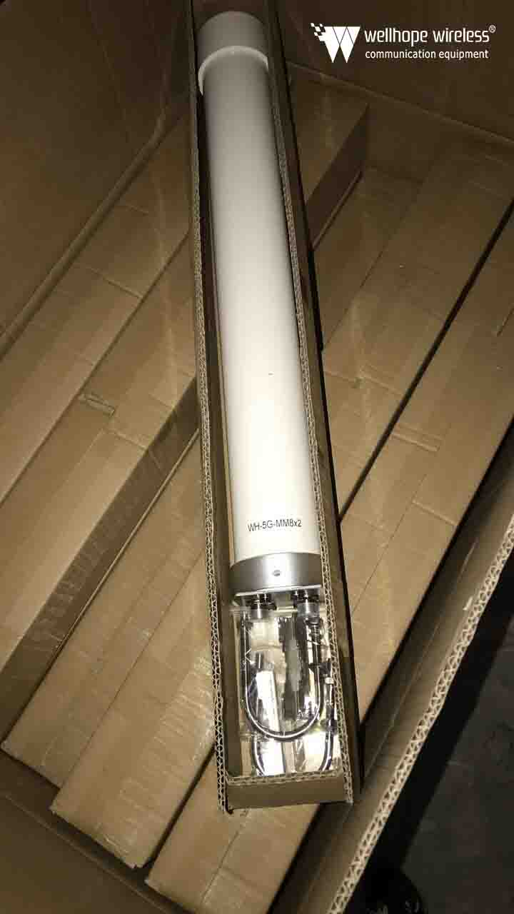
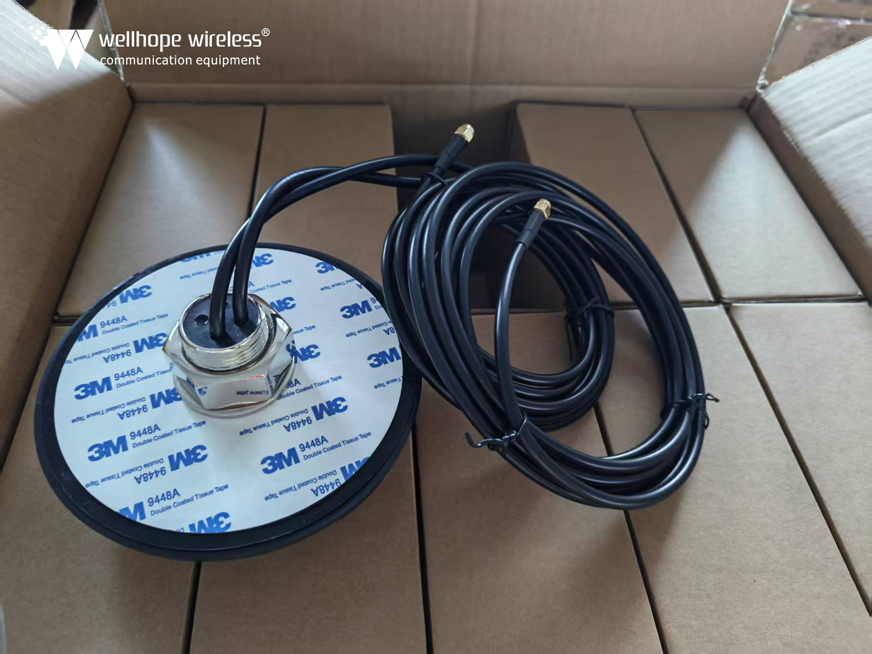
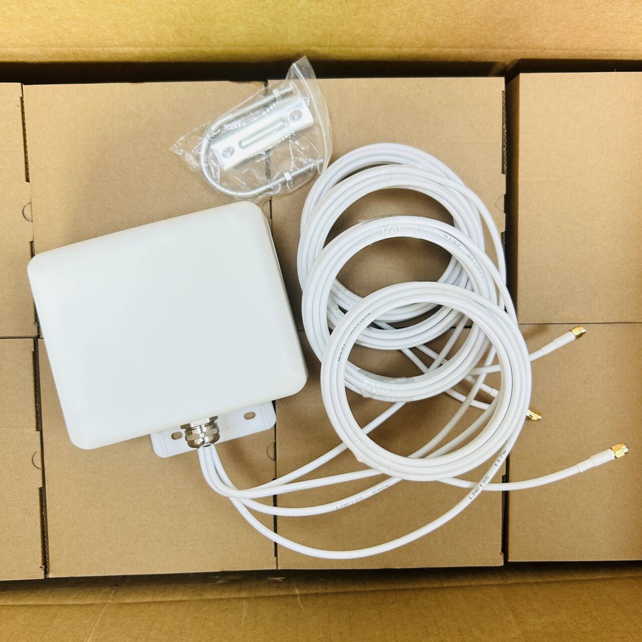
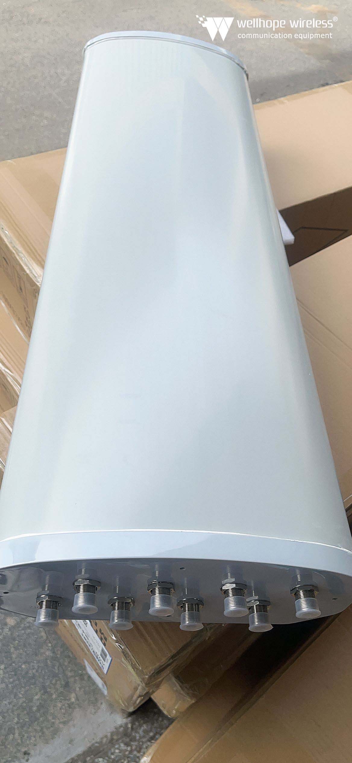
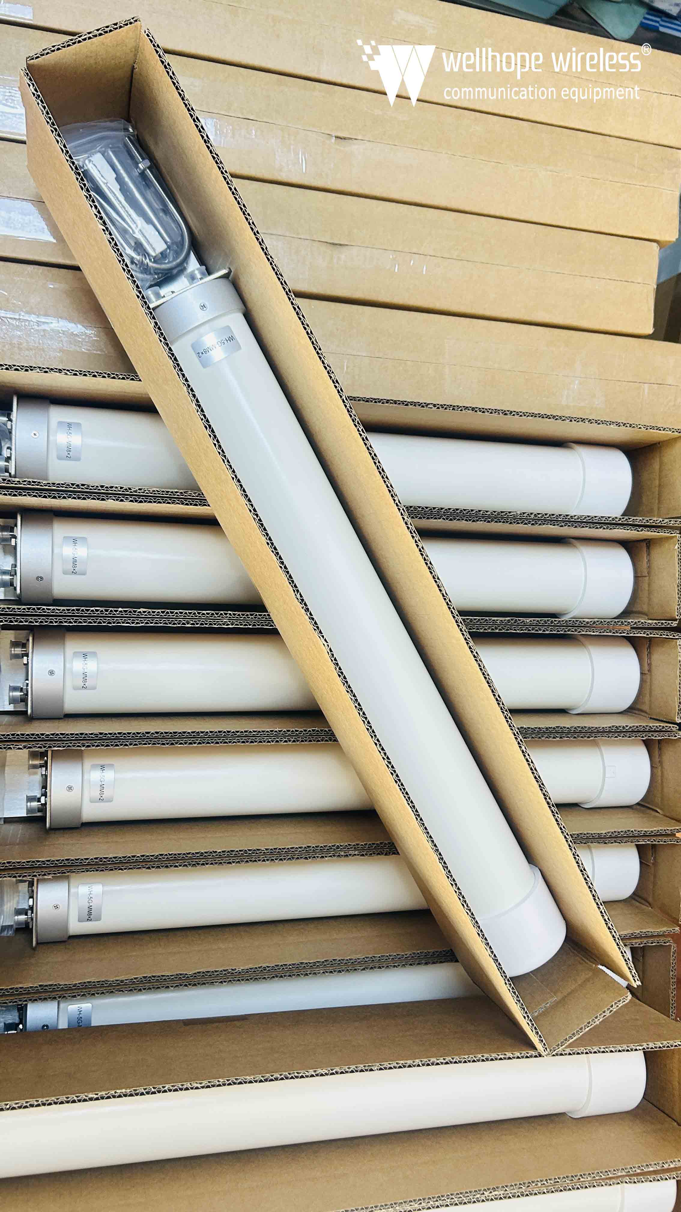
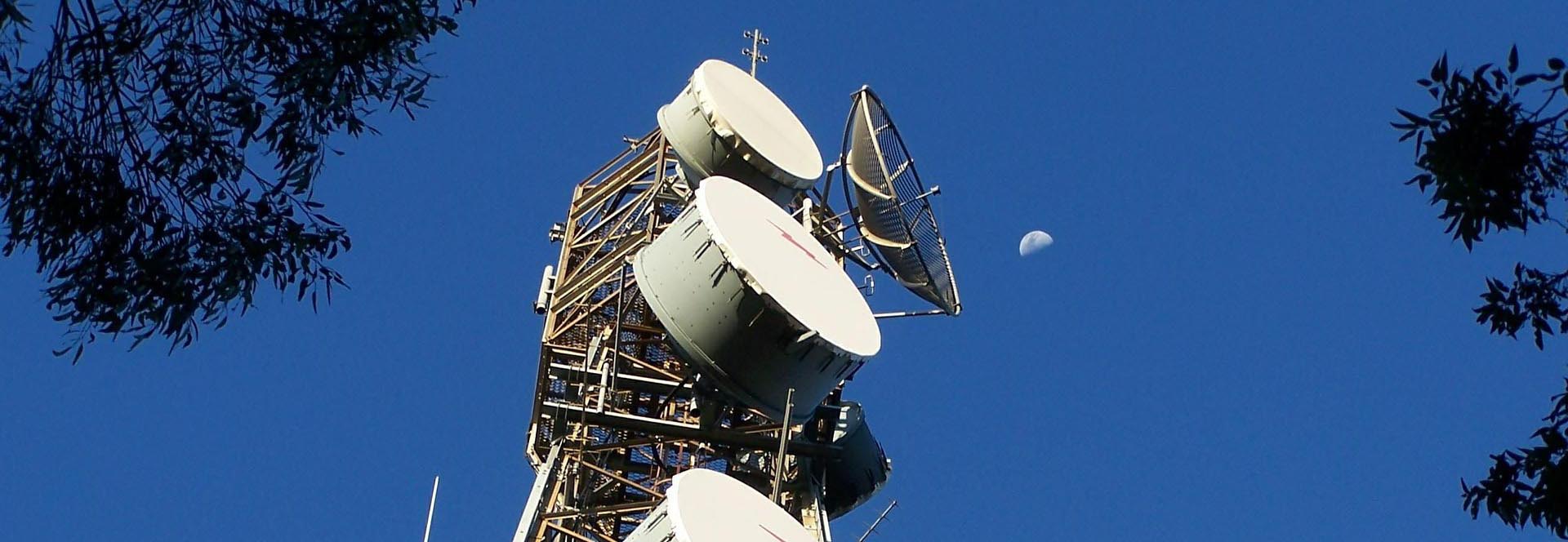
The reasons for the use of antenna covers and classification details https://www.whwireless.com/ Estimated 5 minutes to finish reading Outdoor antennas are often attacked by wind and rain, resulting in the reduction of antenna transmission capacity, so we also need a protective device to maintain the normal operation of the antenna. Antenna cover is a structure to protect the antenna system from external environment, it has good electromagnetic wave penetration characteristics in electrical performance, mechanical performance can withstand the role of external harsh environment. This article will discuss the purpose and classification of antenna masks from the point of view of why they are needed. Radome for parabolic antenna, 400mm diameter I. Why do we need a radome? 1、Protect the antenna system from wind and rain, ice and snow, sand and dust and solar radiation, make the antenna system work more stable and reliable, at the same time reduce the antenna system wear, corrosion and aging, prolong the service life. 2, eliminate wind load and wind moment, reduce the driving power of the rotating antenna, reduce the weight of the mechanical structure, reduce inertia and improve the inherent frequency. 3、The relevant equipment and personnel can work inside the cover, not affected by the external environment, improve the efficiency of the use of equipment and improve the working conditions of the operator. 4, for high-speed flight of the aircraft, the radome can solve the high temperature, aerodynamic load and other load to the antenna brought about by the problem. However, it should be noted that the radome is an obstacle in front of the antenna, which will produce absorption and reflection of the antenna radiation wave, change the free space energy distribution of the antenna, and affect the electrical performance of the antenna to some extent. → Cause analysis. The reflection of the antenna hood wall and the uneven part of the bypass will cause the antenna main flap electric axis offset, thus producing aiming error; The antenna hood on high frequency energy absorption and reflection will cause transmission loss, thus affecting the antenna gain (receive when the system noise temperature increase); The antenna hood caused by the antenna flap distortion, so that the antenna main flap width change, zero depth increase and side flap level increase. 1710~2700MHz 6dBi gain omni-directional PRO series antenna, N-type female connector, glass fiber radome Second, the classification of the radome 1, From the use of the two categories of aviation type and ground (including ship) type. 2, from the electrical according to the antenna radiation wave incidence angle is divided into vertical incidence radome and large incidence angle radome. Radiation wave rays and the angle of the wall normal for the angle of incidence. The angle of incidence is less than 30°, called vertical incidence radome. Antenna in the hood scan to any position, the incidence angle of c...
View More

 News
News