Detailed analysis of the 8 core parameters
of antennas
2021-11-26 www.whwireless.com
Estimated 6 minutes to finish reading
Antennas have always been the key focus of
attention in the field of connectivity products, we have previously carried out
a preliminary introduction and analysis according to the type of antenna, but
in this large segment of the antenna, it is necessary to know further its key
parameters in order to understand more deeply the advantages and use of each
type of antenna. The following parameters are divided into two main parts: radiation parameters and circuit parameters, which we will analyse precisely and
quickly introduce the meaning of them.
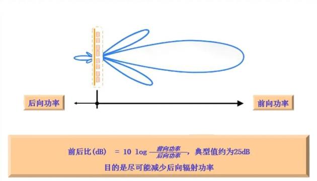
The antenna's front-to-back ratio is the
ratio of the power flux density in the maximum radiation direction of the main
flap (specified as 0°) to the maximum power flux density near the opposite
direction (specified as within 180°±30°) F/B=10log(front-to-back power/backward
power).
Electric down tilt angle
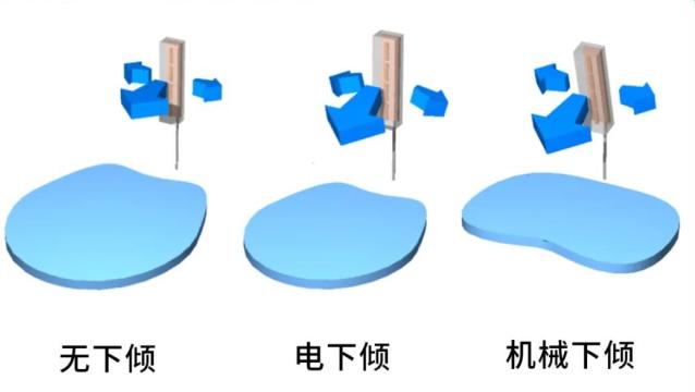
The electric down tilt angle is the maximum radiation pointing on the vertical radiation surface of the communication antenna and the angle of the antenna normal.
Communication antenna is divided into fixed
down tilt antenna and electric tilt antenna according to whether it supports
electric down tilt adjustment: fixed down tilt antenna refers to the fixed down
tilt antenna generated by the amplitude and phase assignment of the antenna
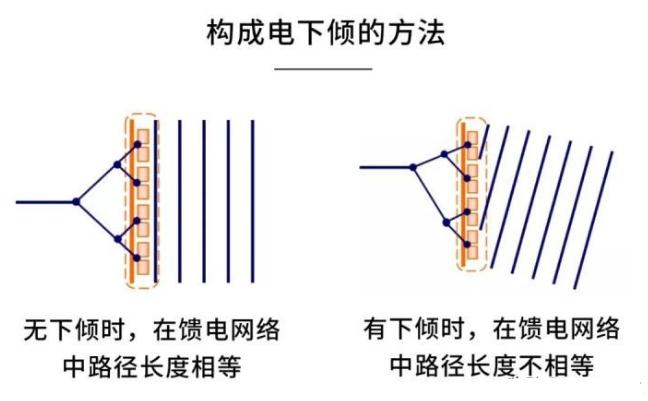
radiation unit array according to the wireless coverage demand; and electric
tilt antenna refers to the phase difference of different radiation units in the
array through phase shifting unit to produce different radiation main flap down
tilt state, usually the down tilt state of electric tilt antenna Only within a
certain adjustable angle range.
Wave speed width
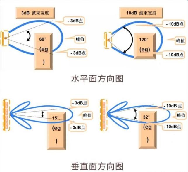
In the direction of the diagram usually
have two flaps or more flaps, which is the largest flap called the main flap,
the rest of the flap called the secondary flap. The angle between the two
half-power points of the main flap is defined as the width of the flap of the antenna directional diagram. Called half power (angle) flap width. The narrower
the main flap flap width, the better the direction, the stronger the
anti-interference ability. Generally speaking, the narrower the main flap beam
width of the antenna, the higher the antenna gain.
Antenna gain
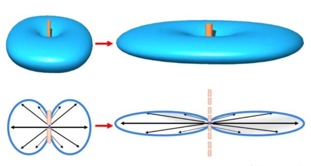
Gain and antenna size and beam width of the
relationship.
The flatter the "tyre", the more
concentrated the signal, the higher the gain, the larger the antenna size, the
narrower the beamwidth.
→ 3 important points to pay attention to in
particular
1. Antennas are passive devices and do not
generate energy. Antenna gain is only the ability to focus energy effectively
in a particular direction to radiate or receive electromagnetic waves.
2, the gain of the antenna is generated by
the superposition of oscillators. The higher the gain, the longer the length of
the antenna. Gain increase 3dB, double the volume.
3, the higher the gain of the antenna, the better the directionality, the more concentrated the energy, the narrower the wave flap.
Antenna circuit parameters
Voltage VSWR
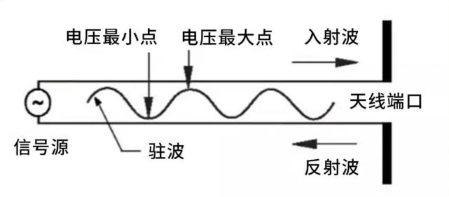
Antenna voltage standing wave ratio is the antenna as a non-consumptive transmission line load, along the transmission
line voltage standing wave generated on the graph, the maximum value and the
minimum value of the ratio.
VSWR, is due to the incident wave energy
transmission to the antenna input is not all absorbed (radiation) generated by
the reflected wave iteration and formed. the larger the VSWR, the greater the
reflection, the worse the match. In the mobile communication system, the
general requirement of VSWR is less than 1.5.
Input Impedance
Antenna input signal voltage and signal
current ratio, known as the antenna input impedance. General mobile
communication antenna input impedance of 50Ω.
Input impedance and antenna structure, size
and wavelength, in the required working frequency range, so that the input
impedance of the imaginary part is very small and the real part is quite close
to 50Ω, which is the antenna and feed line in a good impedance matching must
be.
Third-order intermodulation
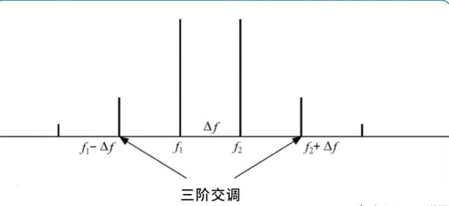
Intermodulation phenomenon is by the
frequency band outside the two or more carrier frequencies mixed in the band
after the new frequency component, causing the system performance decline
phenomenon. Higher power transmit signals are usually mixed to produce an
intermodulation signal that ends up in the receive band, where the signal
received by the base station antenna is usually of lower power. If the
intermodulation signal has a similar or higher power than the actual received
signal, the system can mistake the intermodulation signal for the real signal.
Isolation
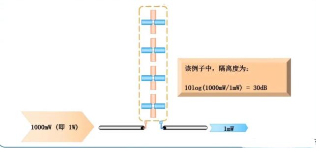
Isolation represents the proportion of the
signal fed to one port (one polarisation) of a dual polarisation antenna that
appears in the other port (the other polarisation).
www.whwireless.com


 News
News
