 5G network antenna
Antenna gain calculation
2021-10-22 www.whwireless.com
Estimated 6minutes to finish reading
Antenna gain is a very important part of the antenna knowledge structure, of course, is also one of the important parameters for the selection of antennas. Antenna gain for the quality of operation of the communication system also plays a big role, in general, the gain is mainly dependent on reducing the width of the vertical-oriented radiation flap, and in the horizontal plane to maintain the omnidirectional radiation performance.
A, the definition of antenna gain.
Antenna in a certain direction of the radiation power flux density and reference antenna in the same input power when the maximum radiation power flux density ratio.
→ Need to pay attention to the following points.
(1) if not specially marked, antenna gain are referred to the maximum radiation direction gain.
(2) Under the same conditions, the higher the gain, the better the directionality, the farther the wave propagates, i.e. the distance covered increases. However, the wave speed width will not be compressed, the narrower the wave flap, thus leading to poor uniformity of coverage.
(3) Antennas are passive devices and do not generate energy. Antenna gain is only the ability to effectively concentrate energy to a particular direction of radiation or receive electromagnetic waves.
Second, the formula for calculating antenna gain
We can learn from the definition of antenna gain, antenna gain and antenna directional map has a close relationship, the narrower the main flap, the smaller the secondary flap, the higher the gain.

(1) For parabolic antenna, the gain can be approximated by the following equation.
G(dBi) = 10Lg{4.5×(D/λ0)^2}
*Note that
D: paraboloidal diameter
λ0: central operating wavelength
4.5: Statistically validated empirical data
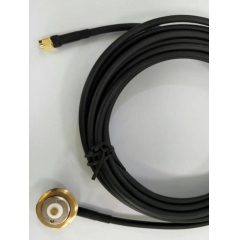
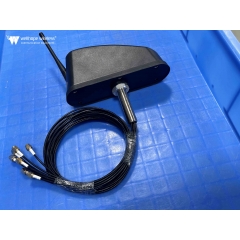
2.4 GHz 13 dBi bipolar omnidirectional MIMO antenna - N-type female connector
(2) For an upright omnidirectional antenna, the following equation can also be used to approximate
G(dBi) = 10Lg{2L/λ0}
*Note that
L: Antenna length
λ0: central working wavelength
Third, gain and transmitting power
The RF signal output from the radio transmitter, through the feeder (cable) to the antenna, by the antenna in the form of electromagnetic wave radiation out. After the electromagnetic wave reaches the receiving place, it is received by the antenna (only a very small part of the power is received) and sent to the radio receiver through the feeder. In the engineering of wireless networks it is therefore very important to calculate the transmitting power of the transmitter and the radiation capacity of the antenna.
The transmitted power of a radio wave is the energy in a given frequency band range and is usually measured or measured in two ways.
Power (W): a linear level relative to 1 watt (Watts).
Gain (dBm): a proportional level relative to 1 milliwatt (Milliwatt).
→ The two expressions can be converted to each other.
dBm = 10 x log[power mW]
mW = 10^[gain dBm / 10 dBm]
In wireless systems, antennas are used to convert current waves into electromagnetic waves, and in the process of conversion they also "amplify" the transmitted and received signals. Antenna gain is measured in "dBi".
As the electromagnetic wave energy in the wireless system is generated by the amplification of the transmitting energy of the transmitting device and the antenna superimposed, so the measure of transmitting energy, the best the same measure - gain (dB), for example, the power of the transmitting device is 100mW, or 20dBm; the antenna gain is 10dBi, then.
Total transmit energy = transmit power (dBm) + antenna gain (dBi)
= 20dBm + 10dBi
= 30dBm
Or: = 1000mW = 1W
[3dB rule].
→ Every dB is important in a "low power" system, especially remember the "3dB rule".
Each increase or decrease of 3 dB means doubling or halving the power: -3 dB = 1/2 power
-3 dB = 1/2 power
-6 dB = 1/4 power
+3 dB = 2x power
+6 dB = 4x power
As an example, 100 mW has a wireless transmit power of 20 dBm, while 50 mW has a wireless transmit power of 17 dBm and 200 mW has a transmit power of 23 dBm.
Antenna main parameter indicators
The antenna's front-to-back ratio is the ratio of the power flux density in the maximum radiation direction of the main flap (specified as 0°) to the maximum power flux density near the opposite direction (specified as within 180°±30°) F/B=10log(forward power/backward power).

Electric down tilt angle is the maximum radiation pointing on the vertical radiation surface of the communication antenna and the angle of the antenna normal.
Communication antenna is divided into fixed down tilt antenna and electric tilt antenna according to whether it supports electric down tilt adjustment: fixed down tilt antenna refers to the fixed down tilt angle antenna generated by the amplitude and phase assignment of antenna radiation unit array according to the wireless coverage demand; and electric tilt antenna refers to the phase difference of different radiation units in the array through phase shifting unit to produce different radiation main flap down tilt state, usually the down tilt state of electric tilt antenna Only within a certain adjustable angle range.


In the direction of the diagram usually have two flaps or more flaps, which is the largest flap called the main flap, the rest of the flap called the secondary flap. The angle between the two half-power points of the main flap is defined as the width of the flap (beam) of the antenna direction diagram. Called half power (angle) flap width. The narrower the main flap flap width, the better the direction, the stronger the anti-interference ability. Generally speaking, the narrower the main flap beam width of the antenna, the higher the antenna gain.

Antenna gain and antenna size and beam width of the relationship.
The flatter the "tyre", the more concentrated the signal, the higher the gain, the larger the antenna size, the narrower the beamwidth.
→ 3 important points to pay attention to in particular
1. Antennas are passive devices and do not generate energy. Antenna gain is only the ability to focus energy effectively in a particular direction to radiate or receive electromagnetic waves.
2, the gain of the antenna is generated by the superposition of oscillators. The higher the gain, the longer the length of the antenna. Gain increase 3dB, double the volume.
3, the higher the antenna gain, the better the directionality, the more concentrated the energy, the narrower the wave flap.

The antenna's voltage standing wave (VSWR) ratio is the antenna as a non-consumptive transmission line load, in the transmission line along the voltage standing wave generated on the graph, the ratio of its maximum value to the minimum value.
VSWR ratio is generated, is due to the incident wave energy transmission to the antenna input end is not all absorbed (radiation) generated by the reflected wave iteration and formed. the larger the VSWR, the larger the reflection, the poorer the match. In the mobile communication system, the general requirements of the VSWR is less than 1.5.

Antenna input signal voltage and signal current ratio, known as the input impedance of the antenna. General mobile communication antenna input impedance of 50Ω.
Input impedance and antenna structure, size and wavelength, in the required working frequency range, so that the input impedance of the imaginary part is very small and the real part is quite close to 50Ω, which is the antenna and feed line in a good impedance match must be.
Intermodulation phenomenon is by the frequency band outside the two or more carrier frequencies mixed in the band after the new frequency components, resulting in system performance degradation phenomenon. Higher power transmit signals are usually mixed to produce intermodulation signals that end up in the receive band, where the signal received by the base station antenna is usually of lower power. If the intermodulation signal has a similar or higher power than the actual received signal, the system can mistake the intermodulation signal for the real signal.

Isolation represents the proportion of the signal fed to one port (one polarisation) of the dual polarisation antenna that appears in the other port (the other polarisation).

www.whwireless.com