 5G network antenna
About 5G antenna OTA test method analysis and application
Estimated 8 minutes to finish reading
www.whwireless.com
Test methods of existing antennas
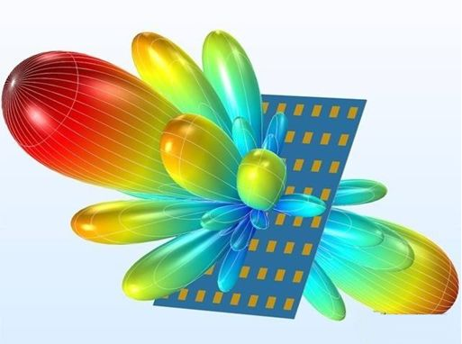
With the deepening of electromagnetic research and the development of electronic technology, the development and application of antennas have penetrated into many fields such as navigation, communication, electronic countermeasures and radar, etc. Multi-beam antennas can form multiple mutually independent transmit or receive beams simultaneously or in time through phased arrays to achieve flexible control of beam shape and rapid switching of beam direction. At present, the most widely used phased array antenna test methods are mainly three: far-field method, near-field method and tight field method.
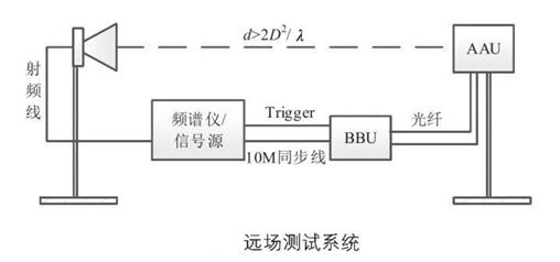
1、Far field test scheme
Far-field test is the most direct test method, when the test distance is far enough, the human wave in the receiving surface is close to the plane wave. The diagram below shows the far-field test system, where the part under test can be rotated 360° in the vertical and horizontal planes, and the test probe position is fixed and can be polarised and rotated. The test system can test the beam assignment directional map and EIRP (Effective Isotropic Radiated Power), EVM (Error Vector Magnitude), occupied bandwidth, EIS (Effective Isotropic Sensitive), and EIS (Effective Isotropic Sensitive) of the 5G base station antenna. Isotropic Sensitive, effective omnidirectional sensitivity) and other RF radiation indicators.
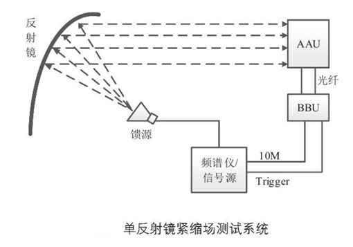
2、Tight field test programme
The tight field test is a far-field test method, which can use a reflector or lens to convert the spherical wave from the feed source at the focal point into a plane wave, so as to achieve the far-field test in a limited physical space. The figure below shows a parabolic single reflector constrained field test system that can test the beam assignment direction map and EIRP, EVM, occupied bandwidth, ACLR (Adjacent Channel LeakagePower ration), EIS, ACS (Adjacent Channel Selectivity) of a 5G base station antenna. Channel Selectivity) and other RF radiation indicators.
3、Near-field test solution
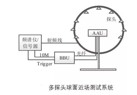
Multi-probe spherical near-field test solution
Near-field test in the measured antenna radiation near-field area to collect the amplitude and phase information, and then through the near and far field conversion algorithm to collect data into the far field direction map. The multi-probe spherical near-field test system is shown in the diagram below, where a large number of probes are arranged along the circumference of the radiated near-field of the DUT, and the DUT only needs to be rotated by 180 degrees to capture data from the entire radiated sphere. The system is capable of testing the beam assignment direction of a 5G base station antenna in CW (Continuous Wave) mode.
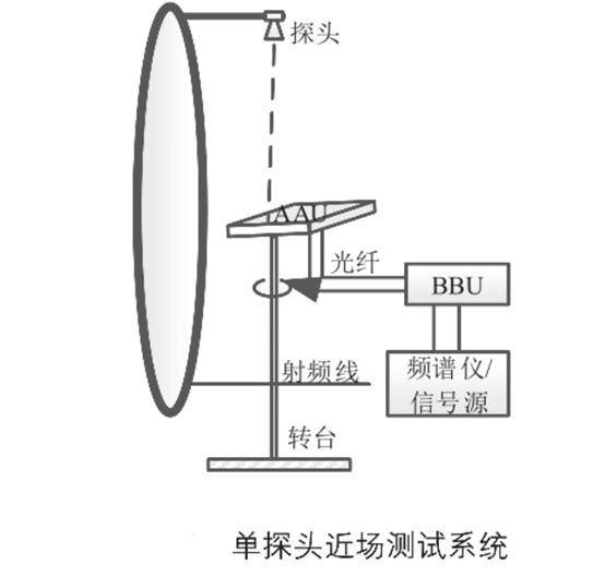
Single probe near-field test system
Single probe near-field testing is less efficient than multi-probe spherical near-field testing, but it is simpler and requires less space. The small near-field test system shown in the diagram below, the test piece can be rotated in the horizontal plane, the probe can be rotated in the vertical plane, the system in the two rotation axis can be collected in a radiation sphere beam assignment direction map, but also can test the RF radiation indicators in the business signal mode, but the processing of test results need further analysis.
Comparison of the advantages and disadvantages of each test solution
The advantages of far-field testing are: because the receiving antenna is farther away from the transmitting antenna than the far-field criterion, the electromagnetic wave propagates from the transmitting antenna to the receiving antenna in an approximate plane wave, the collected data does not require near and far-field conversion, the test equipment can transmit high-power signals, can test modulated broadband signals, support user testing, etc. The disadvantage is: because the test distance needs to be greater than the far-field criterion, so the test site covers an area of large, high construction costs. The further the test distance is, the closer the electromagnetic radiation is to the plane wave, but at the same time it will bring the problem of too much space loss. In addition, as the far-field test generally has only one probe, so a single test can only draw a section of the antenna radiation sphere, if you want to get the whole radiation sphere of the 3D directional map, you need to test on different sections several times, test time and test costs increased significantly.
The advantage of tight field testing is that the site size is significantly reduced compared to the far field, thus greatly reducing site construction costs and measurement path loss. The test results are closest to those of direct far-field testing, allowing testing of CW waves and operational signals. Thanks to the reduced path strength loss, it can measure more RF radiation metrics than the far-field solution. The disadvantages are: similar to the disadvantages of far-field testing, the 3D directional map is less efficient, in addition to the higher cost of the reflector and later maintenance.
The advantages of multi-probe spherical near-field testing are: small footprint, 3D directional map can be given in a single test, high test efficiency, space loss, CW mode directional map test results are close to the far-field test results. The disadvantages are: the upper limit of the received power of the test system is low, and when the 5G base station under test transmits at full power, the test receiving equipment must be front attenuated; the measurement data needs to be post-processed for near- and far-field conversion; the near- and far-field conversion requires a reference phase, and the measurement results in the service signal mode are not satisfactory at present due to the problem of the reference phase.
The advantages of single-probe near-field testing are: it takes up very little space, the construction cost of the darkroom is low, the structure of the turntable is simple, the equipment under test can be installed and dismantled in a portable way, the space loss is low, and the results of the CW mode directional map test are closer to those of the far-field test. The disadvantages are: due to the simple structure, the antenna back flap data acquisition is not complete; only one test probe, testing 3D directional map is not as efficient as multi-probe spherical near field; the collected data need to be converted to near and far field later