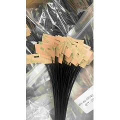
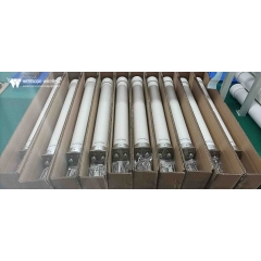
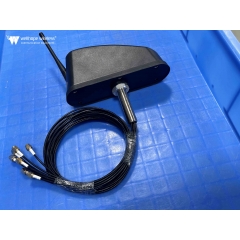
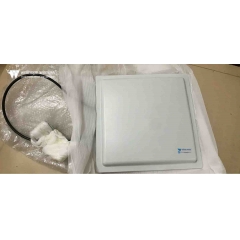
 High gain antenna
How do antennas actually work?
2021-9-16 www.whwireless.com
Estimated 8 minutes to finish reading
Antennas are widely used in telecommunications, for example in radio communications, radio and television.
Antennas pick up electromagnetic waves and convert them into electrical signals, or pick up electrical signals and radiate them as electromagnetic waves.
In this article, let's take a look at the science behind antennas.

If we have an electrical signal, how do we convert it into an electromagnetic wave?
You probably have a simple answer in mind: that is to use a closed wire which, with the help of the principle of electromagnetic induction, will be able to generate a fluctuating magnetic field and an electric field around it.

However, this fluctuating field around the source is of no use in the transmission of the signal.
Here the electromagnetic field does not propagate, it just fluctuates.
In an antenna, the electromagnetic waves around the source need to be separated from the source and they should propagate.

Before we look at how to make an antenna, let's understand the physics of an antenna.
Wave separation considers the placement of a positive charge and a negative charge. This pair of charges arranged very close together is called a dipole, and they obviously produce an electric field as shown in the diagram.

Assuming that these charges are as shown, oscillating at the midpoint of their path, the velocity will reach a maximum and at the end of their path, the velocity will be zero, and due to the change in velocity, the charged particles will experience successive accelerations and decelerations.

The challenge now is to find out how to make the electromagnetic field vary due to this motion.
Let us focus on just one electric field line that expands and deforms in front of the wave that forms at time zero, after a time period of one-eighth.
As shown in the diagram.


You may be surprised to expect a simple electric field to be shown at this location as shown below.

Why does the electric field expand to form an electric field like this one?
It is because accelerating or decelerating charges produce some electric field memory effect and the old electric field does not easily adapt to the new electric field. It will take us some time to understand this memory effect electric field or the accelerating or decelerating charges produced by the kink.
We will discuss this interesting topic in more detail in another article.
If we continue the analysis in the same way, we can see that in a quarter time period the wave front meets at a point where.

After this, the wave fronts separate and propagate.
Note that this changing electric field automatically generates a magnetic field perpendicular to his change.
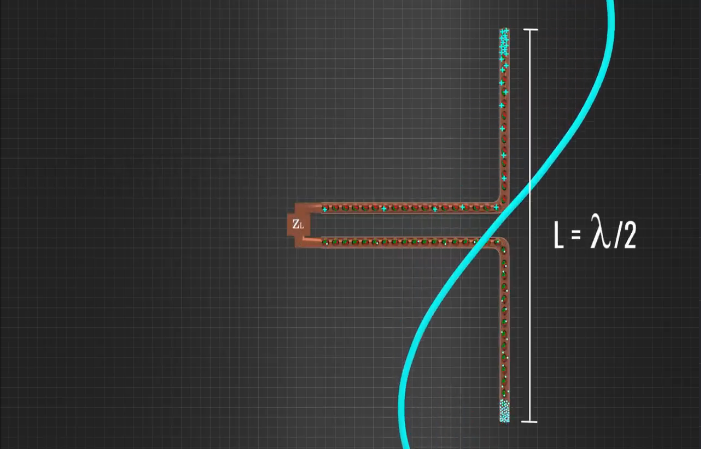
If you plot the variation of the electric field strength with distance, you can see that the wave propagation is intrinsically sinusoidal.

It is interesting to note that the resulting propagation wavelength is exactly twice the length of the dipole.
This is exactly what we need in an antenna; in short, if we can arrange oscillating positive and negative charges, we can make an antenna.
In practice this oscillating charge is easily produced by taking a conducting rod bent in the centre and applying a voltage signal to the centre, assuming this is a time varying signal, consider a situation where at moment 0 due to the voltage the electron will move out of the right side of the dipole and will be accumulated on the left side.
This means that the other end of the losing electron will automatically be positively charged.

This arrangement produces the same effect as the previous dipole charge case, i.e. there is a positive and negative charge at the end of the wire, and as the voltage changes with time the positive and negative charges travel back and forth, thus producing wave propagation.

We have now seen how the antenna works as a transmitter, the frequency of the transmitted signal will be the same as the frequency of the applied voltage signal: the
Since the propagation travels at the speed of light, we can easily calculate the wavelength of propagation at.

For perfect transmission, the length of the antenna should be half the wavelength. The operation of the antenna is reversible and it can work like a receiver.
If the propagating electromagnetic field hits it, we will use the same antenna again and apply an electric field at that point, electrons will accumulate at one end of the rod, this is the same as an electric dipole, when the applied electric field changes the positive and negative charges accumulating at the other end, the changing charge accumulation means that a changing voltage signal is generated at the centre of the antenna.
This voltage signal is the output of the antenna when it is operating as a receiver, and the frequency of the output voltage signal is the same as the frequency of the received a.m. wave.
It is clear from the electric field structure that the antenna should be half the size of the wavelength in order to obtain the desired reception.
In all this discussion we have seen that the antenna is an open circuit, now let us look at some actual antennas and how they work.
In the past, TV reception used a dipole receiving antenna with a coloured strip as the dipole receiving antenna, this antenna also needed a reflector and guide to gather the signal on the dipole, this complete structure was known as a Yagi-Uda antenna.

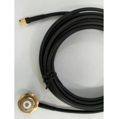
The dipole antenna converts the received signal into an electrical signal and these electrical signals are transmitted to the TV unit via a coaxial cable.
Today we have moved on to the Dish TV antenna, which consists of two main components, a parabolic reflector and a low noise block down-converter.

The paraboloid receives the electromagnetic signals from the satellite and focuses them onto the lnbf, which has a special shape and has been specially and precisely designed.
The lnbf consists of a feedhorn, waveguide, PCB and probe.
In the diagram below, you can see how the incoming signal is focused onto the probe through the feedhorn and waveguide
As we saw in the case of the simple dipole, a voltage is induced and the voltage signal so generated is fed to the PCB for signal processing.

For example, the signal is filtered from high to low frequencies and amplified after processing, and this electrical signal is transmitted to the TV unit via a coaxial cable.
If you turn on an Lnb you are likely to find two probes instead of one, the second probe is perpendicular to the first, meaning that the available spectrum can be used twice by sending horizontal or vertical polarisation.

One probe detects the horizontally polarised signal and the other detects the vertically polarised signal.
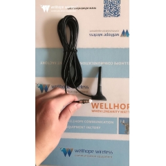
The handset you are holding uses a completely different type of antenna called a patch antenna. A patch antenna consists of a metal patch or strip placed on a ground plane with a piece of dielectric material in the middle, here the metal patch is used as the radiating element and the length of the metal patch should be half the wavelength of the appropriate transmit and receive.
Please note that the description of patch antennas we illustrate here is very basic.