Characteristic difference between PCB and FPC
Expected to finish reading in 8 minutes
Printed circuit board (PCB)
On the insulating base material, a printed board for connecting and printing components between points is formed according to the predetermined design
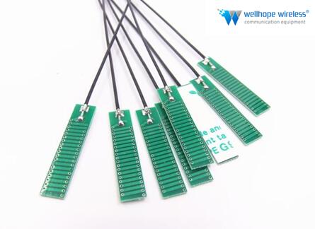
FPC (flexible printed circuit board)
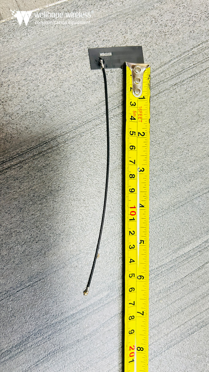
Printed board made of flexible base material. It is one of printed boards
PCB is now an indispensable component in electronic equipment. PCB has different structures and uses, but there are many kinds. PCB can be divided into rigid board and flexible board according to the mechanical properties of whether the substrate can be bent, and rigid flex combined PCB (R-FPC) between them; moreover, PCB can be divided into single panel, double-sided board and multilayer board according to the number of conductive layers.
Flexible printed boards (FPC) include conventional printed boards and IC packaging carrier boards (COB: chip on Flex). At the same time, FPC also has single panel, double-sided board and multi-layer board. At present, there are two kinds of multilayer boards: conventional through hole interconnection multilayer board and multilayer multilayer board (HDI board). FPC also has two kinds of multilayer boards with different structures and processes.
FPC circuit board and PCB comparison, PCB is printed circuit board or printed circuit board, or printed circuit board. FPC is the abbreviation of FPC, also known as soft board, which is a hard board and a soft board. PCB consists of soft board and hard board, but most of them are hard. And FPC is mostly used for lines that are easy to fold, such as cell phone cable and LCD cable. FPC is used for soft light strip, and its folding resistance must be much stronger than PCB.
Characteristics difference between soft board and hard board
In fact, the soft board is not only flexible, but also an important design method of connecting three-dimensional circuit structure. This structure, together with other electronic product design, can widely support various applications. So from this point of view, soft board and hard board are very different.
For the hard board, unless the circuit is made into a three-dimensional shape by means of mold filling, the general state of the circuit board is plane. Therefore, to make full use of the three-dimensional space, the soft board is one of the good plans. In terms of hard board, the common space extension scheme at present is to use slot plus interface card, but the soft board can complete similar structure with transfer design, and the direction adjustment is also relatively flexible. Using one connecting soft board, two hard boards can be connected into a group of parallel line system, or can be turned into any angle to adapt to different product shapes.
The soft board can be connected by terminal connection, but the soft board can also be used to avoid these connection mechanisms. A single soft board, you can use the layout to configure many hard boards and connect them into one. This method reduces the interference of connectors and terminals, and improves the signal quality and product reliability. Figure 3-10 shows the hardware / software combination board constructed from multiple hard boards and soft boards.
Soft board should be the thinnest circuit board because of material characteristics, and thinness is one of the important demands of electronic products. Most of the soft boards are made of thin film materials, so they are also important materials for the thin design of electronic products. Because of the relatively poor heat transfer of plastic materials, the thinner the plastic substrate is, the more favorable it is for heat loss. Generally, the difference between the thickness of the soft plate and the hard plate is more than tens of times, so the heat dissipation rate is also tens of times. The soft plate has this feature. Therefore, when assembling high wattage soft plate parts, many of them will be covered with metal plates to improve the heat dissipation effect.
For the soft plate, when the adjacent distance of the solder joint is close and the thermal stress is large, the elastic property of the solder joint can reduce the stress failure between the joints. This advantage is particularly helpful for surface mount parts without pins, because the contact elastic space is small and easy to occur thermal stress fracture, but through the soft plate assembly can absorb thermal stress, this problem will be greatly reduced.
www.whwireless.com
2020-4-22


 News
News
