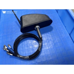
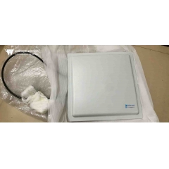
 5G network antenna
One step! Antenna all kinds of calculation formula summary
Estimated 8minutes to finish reading
After introducing the various important parameters of antennas, we are going to enter a deeper area, which is the calculation formulas related to the parameters. Each formula will bring a lot of convenience before and after the installation. These formulas are summarized in this issue, not only can solve various questions during use, but also provide ideas for the subsequent antenna layout.
Antenna gain is a parameter to measure the degree of directionality of antenna radiation direction map. High-gainantenna will give priority to a specific direction of radiation signal. Antenna gain is a passive phenomenon, the power is not increased by the antenna, but simply redistributed so as to provide more radiated power in a certain direction than other isotropic antennas transmit.

↓ The following are some approximate equations for antenna gain.
General antenna
G(dBi) = 10 Lg { 32000 / (2θ3dB,E × 2θ3dB,H)}
In the formula, 2θ3dB,E and 2θ3dB,H are the width of the antenna flaps in the two main planes respectively; 32000 is the statistical empirical data.
Parabolic antenna
G (dBi) = 10Lg{4.5×(D/λ0)2}
In the formula, D is the diameter of the paraboloid; λ0 is the center working wavelength; 4.5 is the statistical empirical data.
Upright omnidirectional antenna
G(dBi) = 10 Lg { 2 L / λ0 }
In the formula, L is the length of the antenna; λ0 is the center working wavelength.
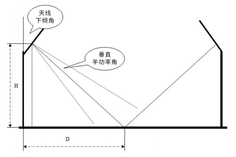
The most important thing about the antenna adjustment is to fine-tune its down-tilt angle (which can solve the problems of weak coverage overlapping coverage, etc.). The following is an introduction to its most original antenna tilt angle calculation method.
The antenna calculation formula for high traffic area (urban area).
Antenna tilt angle = arctag(H/D) + vertical half power angle / 2
Low service area (rural, suburban areas, etc.) antenna formula.
Antenna dip angle = arctag(H/D)
Parameter description.
(1) antenna tilt angle: the angle between the antenna and the vertical direction.
(2) H: antenna height. It can be measured directly.
(3) D: cell coverage radius. Generally D value is determined by road test, in order to ensure the coverage, in the actual design, generally D should be larger to ensure the coverage overlap between neighboring cells.
(4) Vertical half-power angle: the vertical half-power angle of the antenna, generally 10 degrees.
Directional diagram, the ratio of the maximum value of the front and rear flap is called the front and rear ratio, recorded as F / B . Before and after than the larger, the antenna after the radiation (or reception) is smaller. Before and after the ratio of F / B is very simple to calculate:
F / B = 10 Lg {(forward power density) / (backward power density)}
Parameter description: the antenna front-to-back ratio F / B requirements, its typical value is (18 ~ 30) dB, special circumstances require up to (35 ~ 40) dB.
The ratio of signal voltage and signal current at the input of the antenna is called the input impedance of the antenna. Input impedance has a resistance component Rin and reactance component Xin, that is.
Zin = Rin + j Xin
The existence of reactance component will reduce the antenna from the feed line to the signal power extraction, therefore, must make the reactance component as far as possible for zero, that is, the antenna input impedance should be as far as possible for pure resistance.
In fact, even if the antenna is well designed and commissioned, the input impedance always contains a small reactance component value. Input impedance and antenna structure, size and wavelength, half-wave symmetric oscillator is the most important basic antenna .

Its input impedance is Zin = 73.1 + j42.5 (ohm).
When the length is shortened (3-5)%, the reactance component can be eliminated, so that the input impedance of the antenna is pure resistance, then the input impedance is Zin = 73.1 ohms (nominal 75 ohms). Strictly speaking, the purely resistive antenna input impedance is only for the point frequency. By the way, the input impedance of the half-wave folded oscillator is four times the half-wave symmetric oscillator, that is, Zin = 280 ohms (nominal 300 ohms).
The ratio of voltage to current at various locations on an infinitely long transmission line is defined as the characteristic impedance of the transmission line and is denoted by Z. The formula for calculating the characteristic impedance of a coaxial cable is
Z. = [60/√εr] × Log ( D/d ) [ohm
In the formula, D is the inner diameter of the copper network of the outer conductor of the coaxial cable; d is the outer diameter of the coaxial cable core; εr is the relative dielectric constant of the insulation medium between the conductors. Note: Usually Z. = 50 ohms, there are also Z. = 75 ohms.
From the above formula, it is easy to see that the feed line characteristic impedance is only related to the conductor diameter D and d and the dielectric constant εr between the conductors, but not to the feed line length, operating frequency and the load impedance connected to the feed line terminal.
Signal transmission in the feeder, in addition to the resistive loss of the conductor, there is dielectric loss of the insulation material. These two losses increase with the increase in the length of the feeder and the operating frequency. Therefore, a reasonable layout should be as short as possible to shorten the length of the feeder.
The size of the loss per unit length is indicated by the attenuation coefficient β, whose unit is dB / m (decibel / meter), the unit on the technical specifications of the cable mostly used dB / 100m (decibel / hundred meters).
Let the power input to the feeder is P1, the power output from the length of L (m) feeder is P2, transmission loss TL can be expressed as follows.
TL = 10 × Lg ( P1 /P2 ) ( dB )
The attenuation coefficient is: β = TL / L ( dB / m )
In the case of mismatch, both incident and reflected waves exist on the feed line. At the place where the incident and reflected waves are in the same phase, the voltage amplitudes add up to the maximum voltage amplitude Vmax , forming a wave web; while at the place where the incident and reflected waves are in opposite phase the voltage amplitudes subtract to the minimum voltage amplitude Vmin , forming a wave node. The amplitude values of other points are between the wave belly and the wave node. This synthetic wave is called a standing wave.
A, the ratio of the reflected wave voltage and the incident wave voltage amplitude is called the reflection coefficient, noted as R.
R = reflected wave amplitude / incident wave amplitude = (ZL - Z0) / (ZL + Z0 )
Second, the ratio of the wave belly voltage to the voltage amplitude of the wave section is called the standing wave coefficient, also known as the voltage standing wave ratio, noted as VSWR: VSWR = wave belly voltage amplitude.
VSWR = Vmax / Vmin = (1 + R) / (1-R)
The closer the terminal load impedance ZL and characteristic impedance Z0, the smaller the reflection coefficient R, the closer the VSWR is to 1, and the better the match.