 News
News
Easy to understand! After reading it you are half an antenna expert
Estimated 20minutes to finish reading
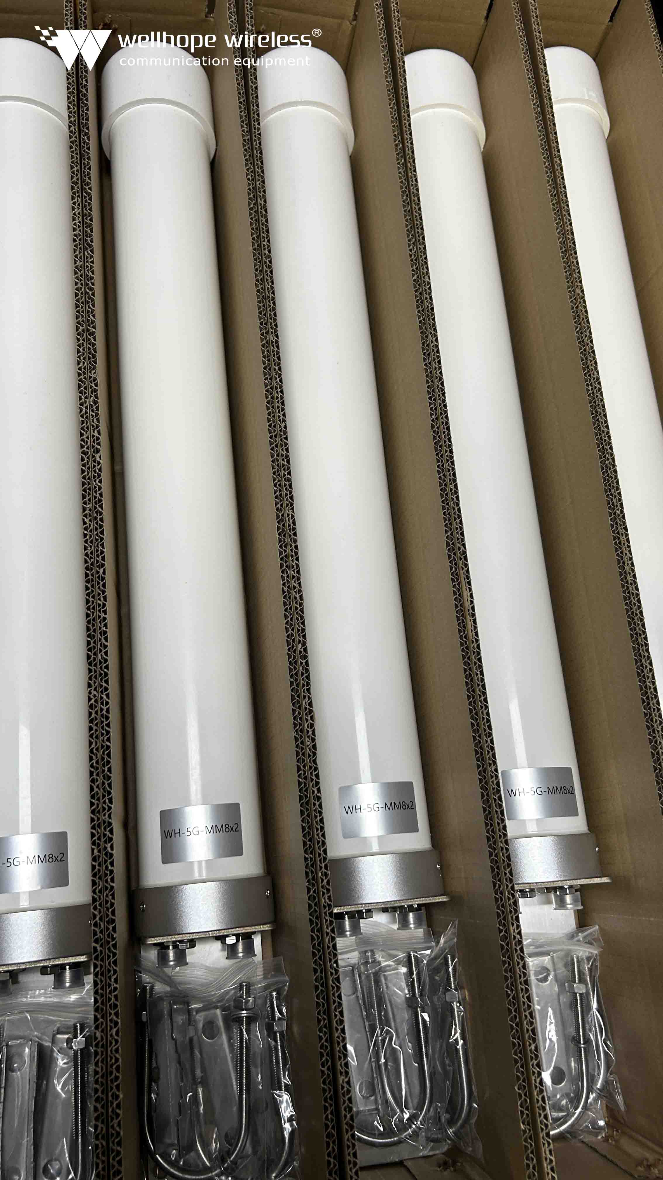
As we all know, antennas are used by base stations and cell phones to transmit signals.
The word antenna in English is Antenna, which originally means tentacles. Tentacles are the two long thin wires on top of an insect's head. Don't underestimate such an inconspicuous thing, but it is the chemical signals sent by these tentacles that convey various social information.
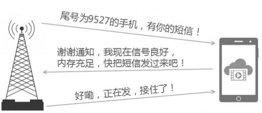
Similarly, in the human world, wireless communication also uses antennas to transmit information, but it is electromagnetic waves that carry useful information. The picture below is an example of a cell phone and a base station communicating with each other.
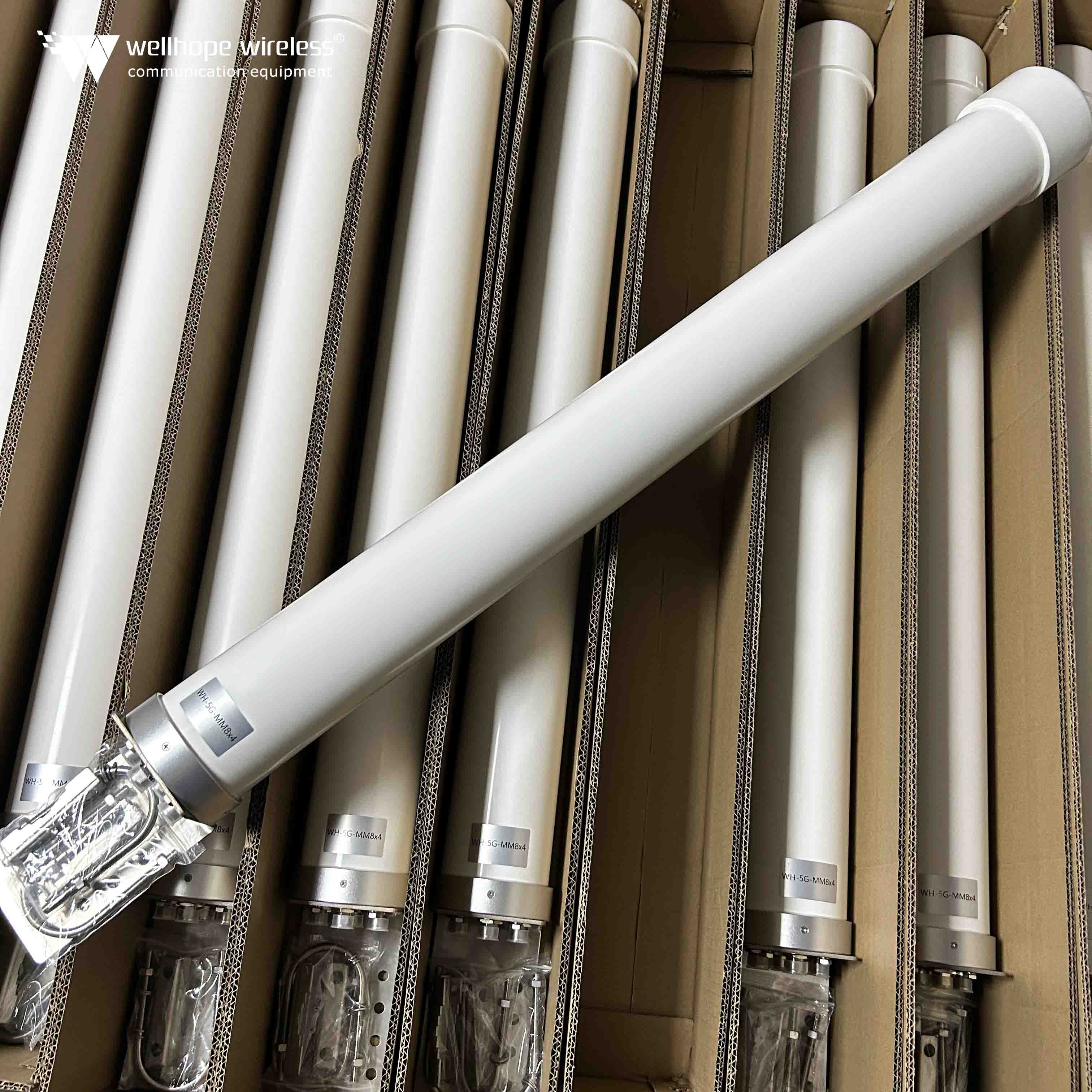
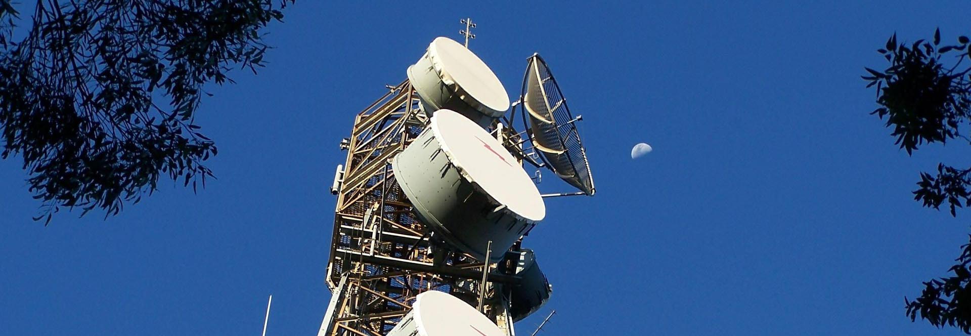
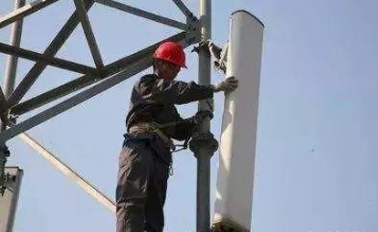
If you raise your head to scrutinize the base station, you will find that at the top of the tower, there are some plate-like things, which is the protagonist of this article: communication antenna, the most often and cell phone direct eye contact is this goods.
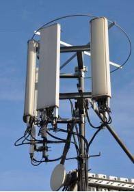
This antenna is called a directional antenna, as the name suggests, is that the signal emission is directed. If it is facing you, the signal just; if you stand behind it, then sorry, not in the service area!
At present, the vast majority of base stations on the use of directional antennas, generally need three antennas to complete 360-degree coverage. To unveil the mysterious veil of this goods, it is necessary to dismantle it to see what is actually loaded inside.
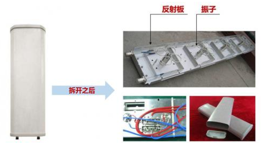
The internal empty, the structure is not complex well, is composed of vibrators, reflector plate, feed network and radome. These internal structures are doing what, how to realize the function of directional transmission and reception of signals?
This is all from the electromagnetic wave to start.
Peeling back the antenna's coat
Antennas are capable of transmitting information at high speeds because they emit electromagnetic waves containing information into the air, traveling at the speed of light and eventually reaching the receiving antenna.
It's like transporting passengers on a high-speed train. If you compare information to passengers, then the vehicle that carries the passengers: the high-speed train is the electromagnetic wave, and the antenna is the equivalent of the station, which manages the dispatching of the electromagnetic wave.
So, what are electromagnetic waves?
Scientists have studied the two mysterious forces of electricity and magnetism for hundreds of years, culminating in Maxwell of England's proposal that an electric current can produce an electric field in its vicinity, a changing electric field produces a magnetic field, and a changing magnetic field produces an electric field. Eventually this theory was confirmed by Hertz's experiments.
With the electromagnetic field in such a periodic transformation, electromagnetic waves radiate and propagate into space. For more details, see the article, "Electromagnetic Waves Cannot Be Seen or Touched, This Young Man's Whimsical Idea Changed the World."
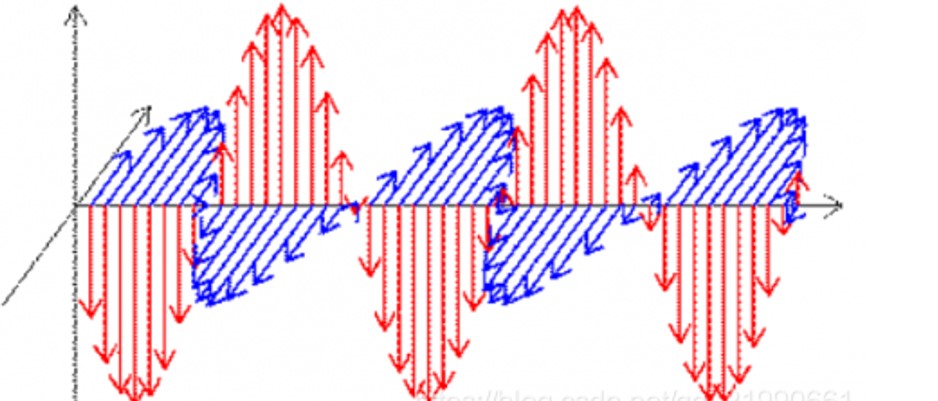
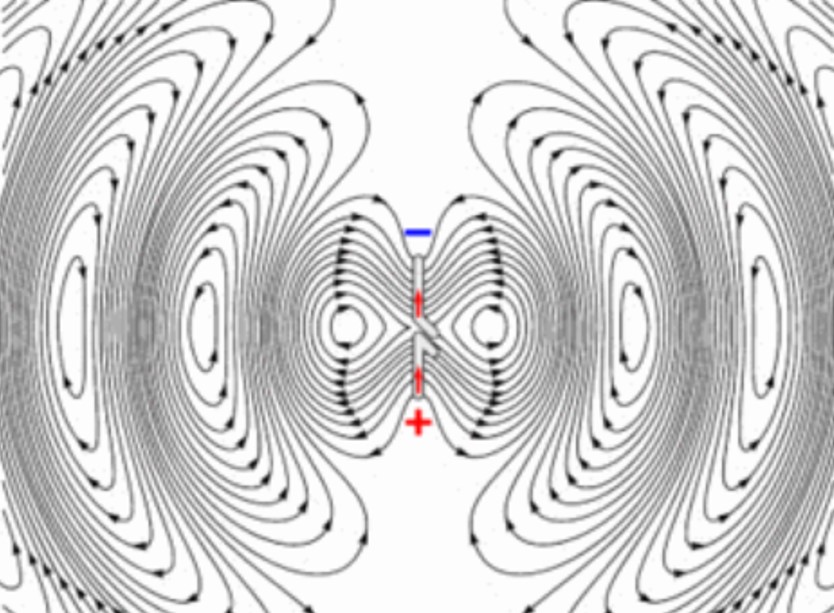
As shown in the figure above, the red line represents the electric field, the blue line represents the magnetic field, and the propagation direction of the electromagnetic wave is perpendicular to the direction of the electric field and the magnetic field at the same time.
So, how does the antenna send these electromagnetic waves out? After looking at the figure below, you will understand.
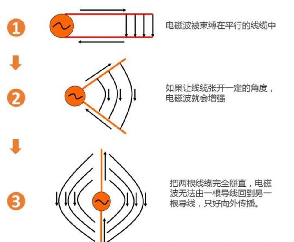
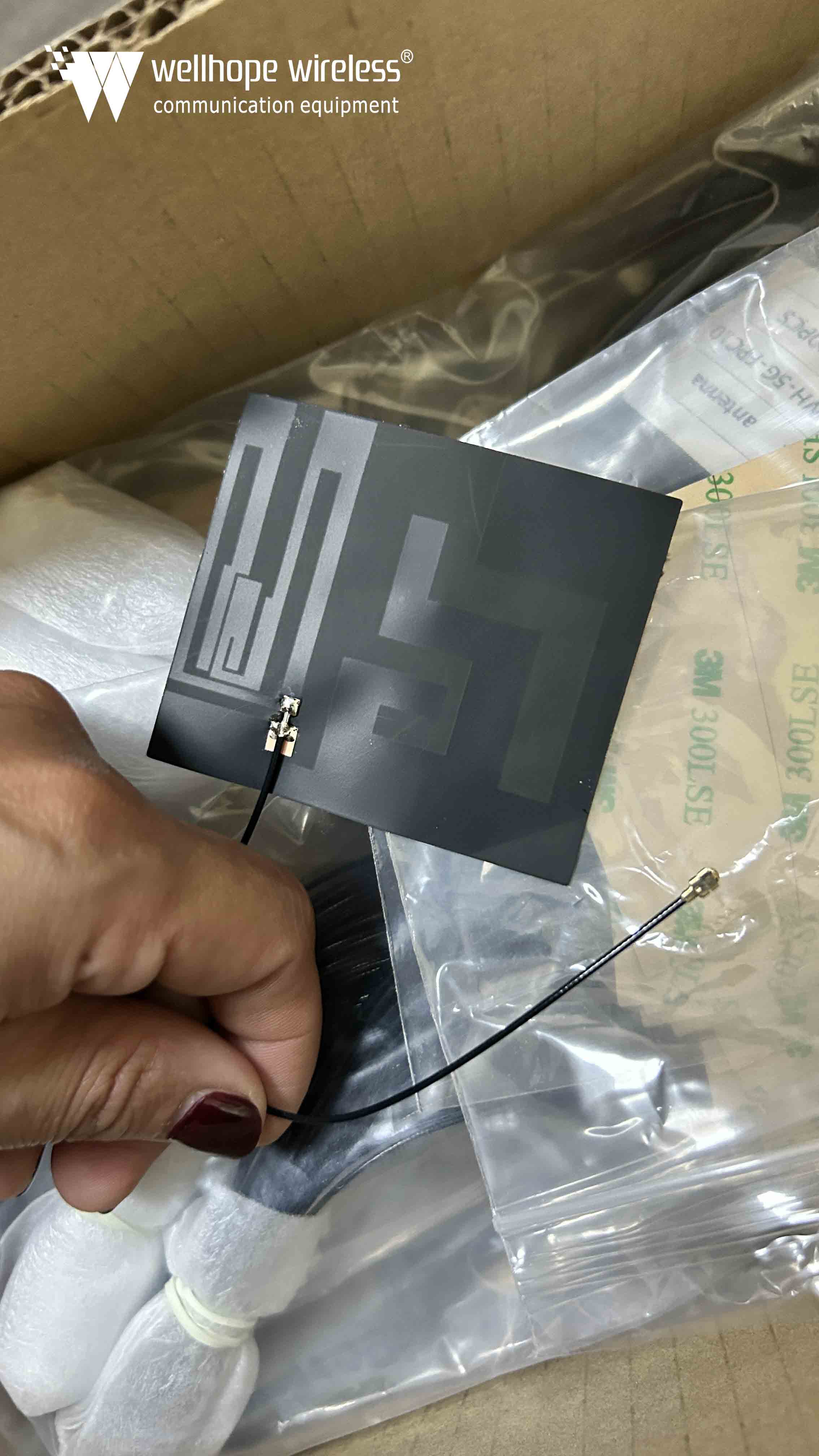
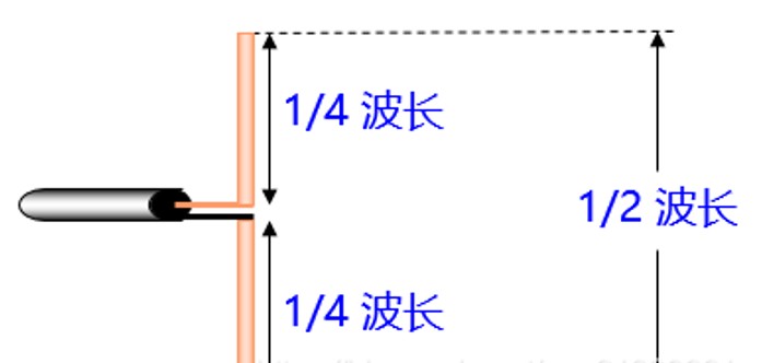
The two wires that generate electromagnetic waves are called "oscillators". In general, the size of the oscillator in half a wavelength when the best results, so it is often called "half-wave oscillator.
With the oscillator, electromagnetic waves can be emitted continuously. This is shown in the figure below:
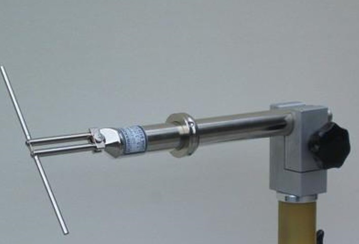
A real oscillator looks like this.
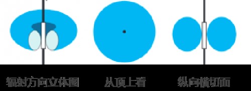
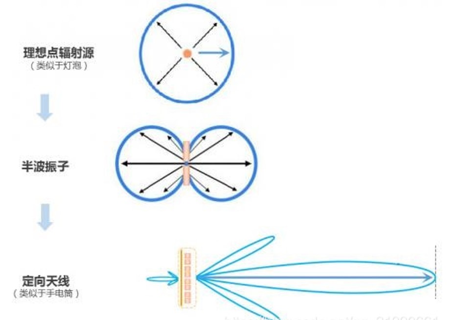
The half-wave oscillator spreads the electromagnetic wave to the space continuously, but the signal strength is not uniformly distributed in the space, like a ring like a tire. The signal is strong horizontally, but weak vertically.
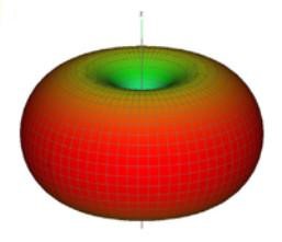
In fact, the coverage of our base station needs to be a little farther in the horizontal direction, after all, need to call the people are on the ground; vertical direction to the high altitude, high in the air there is not much need to fly while brushing Jitterbug people (route coverage is a different topic, by a talk).
Therefore, in the electromagnetic wave energy emission, although the vertical direction of the half-wave oscillator energy has been relatively weak, but also need to further enhance the horizontal direction, the vertical direction to weaken some more.
According to the principle of conservation of energy, energy neither increases nor decreases, and if the emission energy in the horizontal direction is to be enhanced, the energy in the vertical direction must be weakened. Therefore, the only way to flatten the standard half-wave array energy radiation direction map, as shown in the figure below.
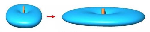
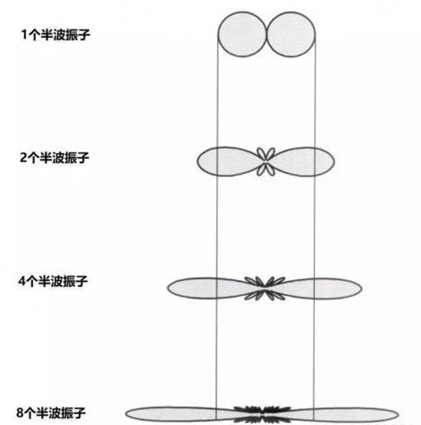
So how to flatten it? The answer is to increase the number of half-wave oscillators. The emission of multiple vibrators in the center convergence, the edge of the energy has been weakened, the radiation direction of the realization of the flattening of the clap, the concentration of energy in the horizontal direction of the purpose.
Directional antennas are most commonly used in general macro base station systems. Generally, a base station is divided into 3 sectors and covered with 3 antennas, each antenna covering a range of 120 degrees.
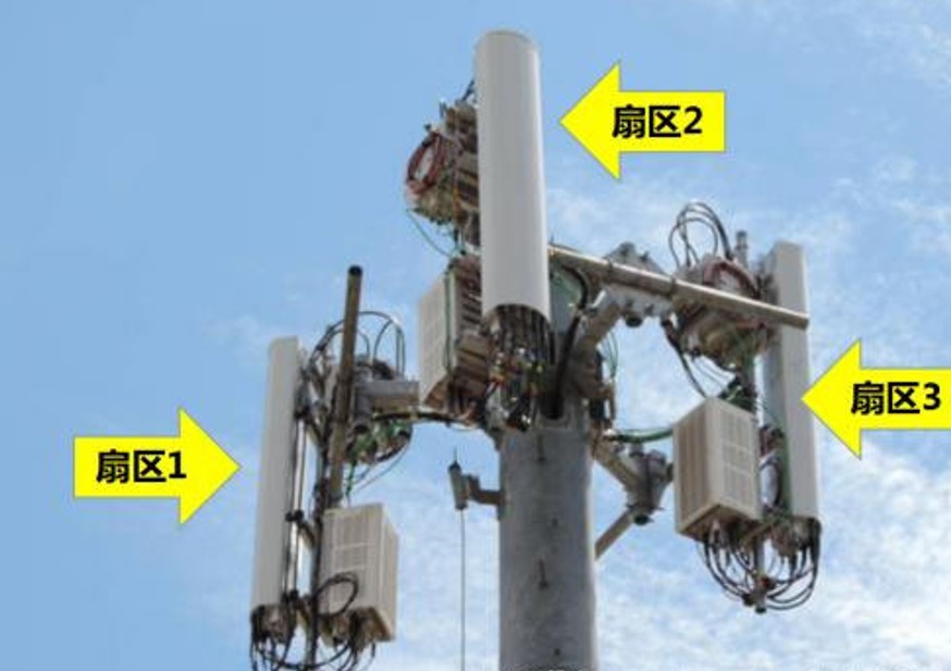
From the figure above we can clearly see that this base station consists of three sectors, using three RF units, which requires three pairs of directional antennas to realize.
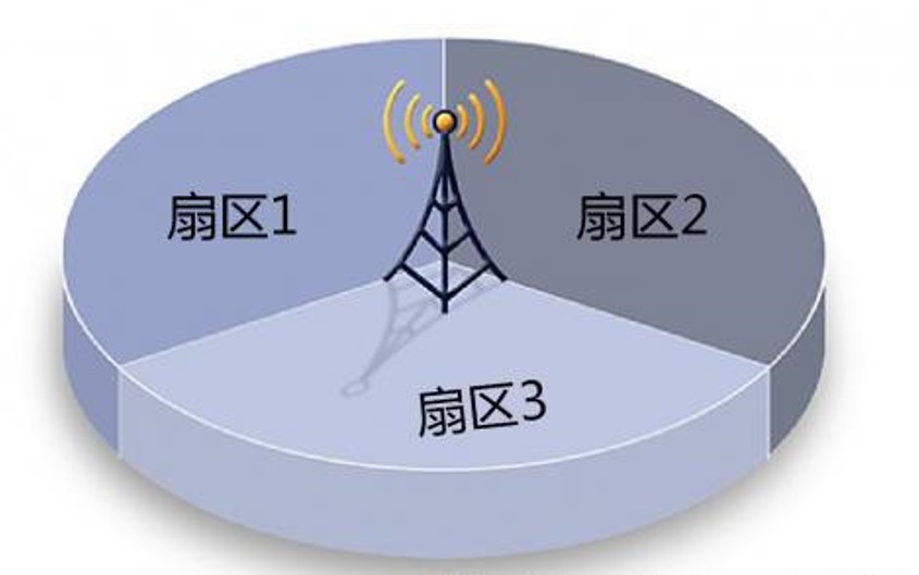
The schematic above is a bit more intuitive. The base station is located in the center of the circle, a large pie is divided into three parts, each of which is a 120-degree sector, so it is called three sectors.
So how does the antenna achieve directional emission of electromagnetic waves?
It's certainly not hard to beat a clever designer. To add a reflector to the oscillator, the signal should be radiated to the other side of the reflection back to it?
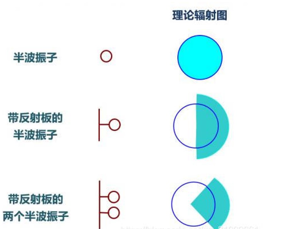
So increase the vibrator so that the electromagnetic wave in the horizontal direction farther, and then increase the reflector to control the direction, after so two toss, the prototype of directional antenna was born, the direction of electromagnetic wave emission into the following figure.
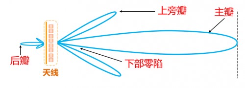
Horizontal side of the main flap to the launch far away, but the vertical direction produces the upper side of the flap and the lower side of the flap, and at the same time due to the reflection is not complete, there is a tail at the back, known as the back of the flap.
At this point, the explanation of the antenna's most important metric: "gain" comes into play.
As the name suggests, gain means that the antenna enhances the signal. It is reasonable to say that the antenna does not need power, just transmit the electromagnetic wave transmitted to it, how can there be "gain"?
In fact, there is no "gain", the key to see with whom, how to compare.
As shown in the figure below, relative to the ideal point radiation source and half-wave oscillator, the antenna can gather the energy in the direction of the main petal, can send the electromagnetic wave farther, equivalent to the main petal direction of the enhancement. That is to say, the so-called gain is in a certain direction relative to the point radiation source or half-wave oscillator.
So, in the end, how to measure the antenna main valve coverage and gain? This requires the introduction of the concept of "beamwidth". We call the main flap on both sides of the centerline electromagnetic wave intensity attenuation to half the range of beamwidth.
Because the intensity attenuation of half, that is, 3dB, so the beam width is also called "half power angle", or "3dB power angle".
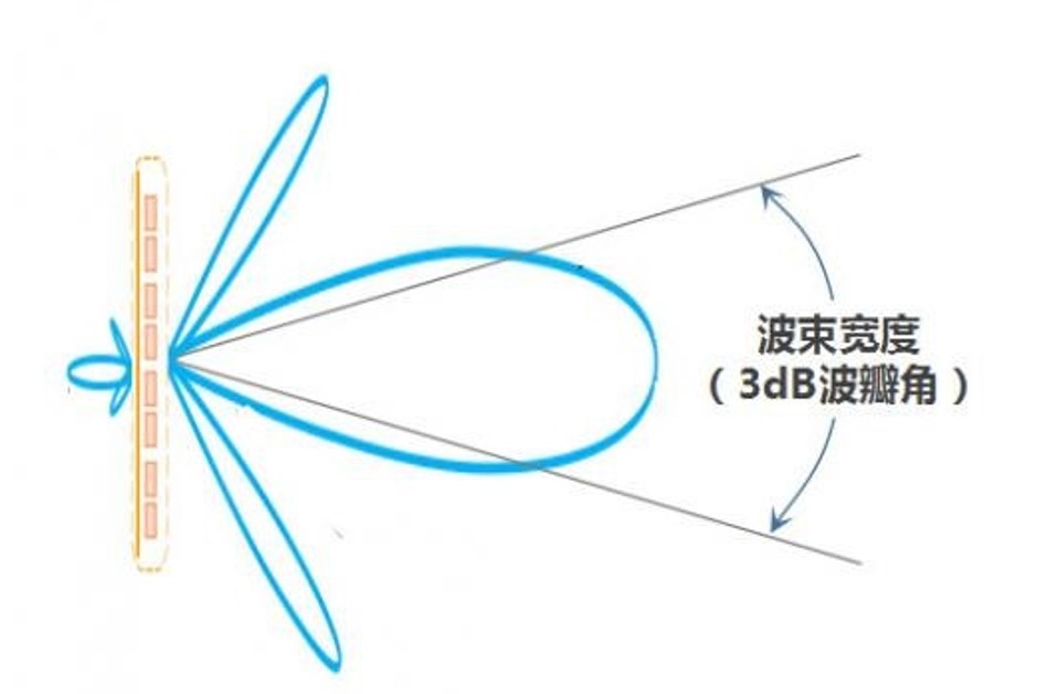
Common antenna half power angle to 60 ° most, there are also some narrower 33 ° antenna. The narrower the half-power angle, the farther the signal spreads in the direction of the main valve, the higher the gain.
Down we combine the horizontal and vertical antenna diagrams, we get a three-dimensional radiation diagram, it looks much more intuitive.
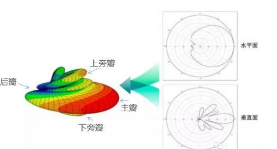
Obviously, the existence of the rear flap destroys the directionality of the directional antenna, is to be minimized. The energy ratio between the front and back flap is called "before and after the ratio", the larger the value the better, is an important indicator of the antenna.
The valuable power of the upper side of the flap is launched into the sky for nothing, but also is not a small waste, so in the design of directional antennas should try to minimize the upper side of the flap suppression.
In addition, between the main flap and the lower side flap there are some holes, also known as the lower part of the zero-sag, leading to the antenna closer to the place of the signal is not good, in the design of the antenna to minimize these holes, known as the "zero-point filling".
Being honest with the antenna
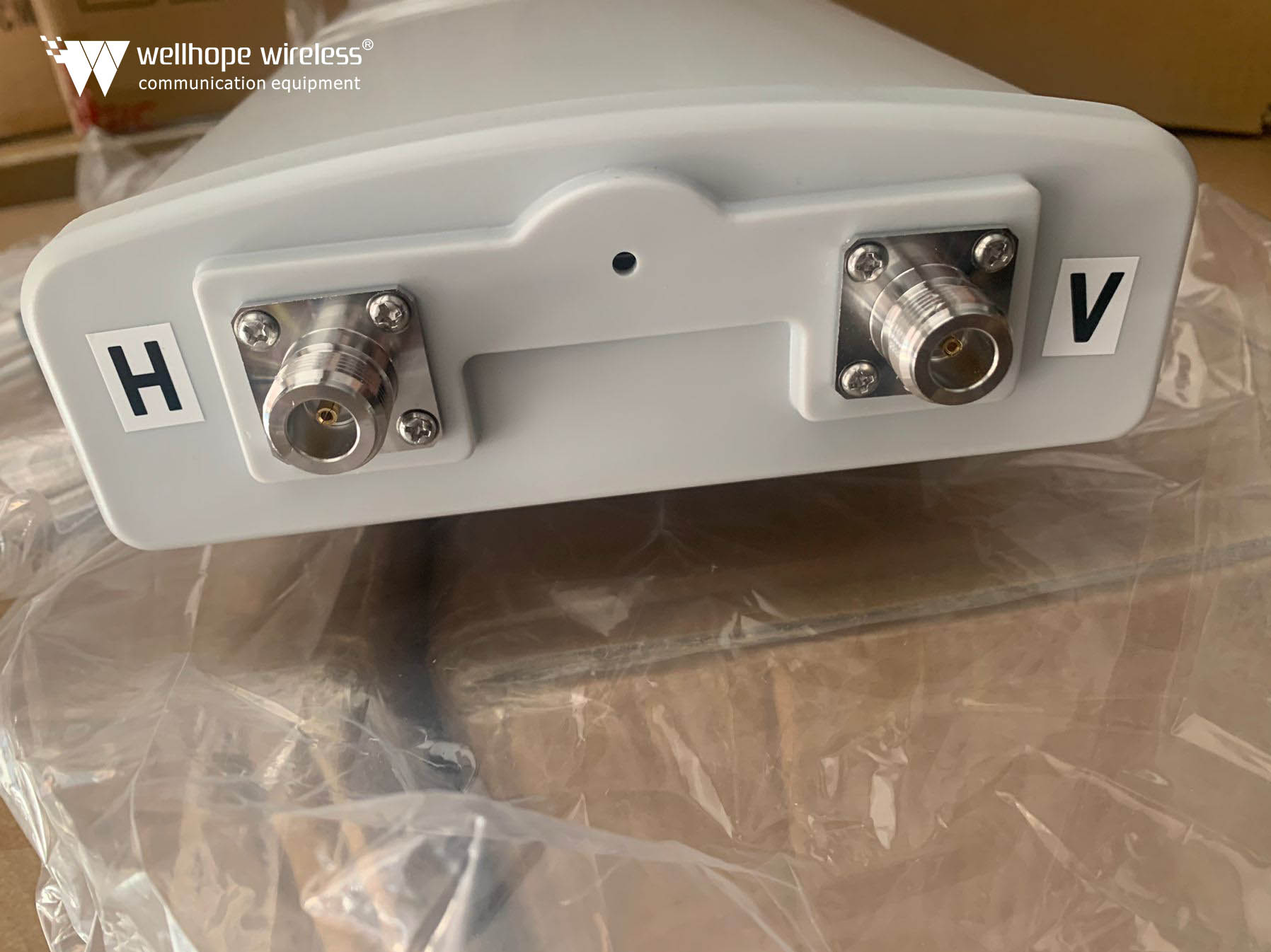
Another important concept of antennas is polarization.
As mentioned earlier, the propagation of electromagnetic waves is essentially the propagation of electromagnetic fields, and electric fields have a direction.
If the direction of the electric field is perpendicular to the ground, we call it a vertically polarized wave. Similarly, parallel to the ground, it is a horizontally polarized wave.
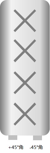
If the direction of the electric field makes an angle of 45° with the ground, we call it ±45° polarization.
Due to the characteristics of electromagnetic waves, decided that the horizontal polarization propagation of the signal in close to the ground will produce polarization current in the earth's surface, so that the electric field signal rapid attenuation, and vertical polarization is not easy to produce polarization current, thus avoiding a significant attenuation of the energy, to ensure the effective propagation of the signal.
As an optimization scheme, now the mainstream antennas are used ± 45 ° two polarization methods superposed by two oscillators in a unit to form two orthogonal polarization wave, known as dual-polarization. This realization in order to ensure the performance at the same time, also makes the antenna integration greatly improved.
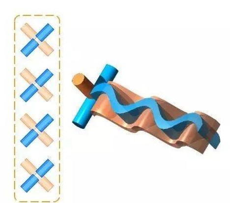
This is the reason why antenna schematics like to draw a number of forks inside, these forks represent both the direction of polarization figuratively and the number of oscillators.
With a high gain directional antenna, hanging directly on the tower can be?
Obviously, hanging low buildings cover too much, no; hanging high, no one in the air, a waste of signal, and let the signal spread too far, the base station can barely accept, but the cell phone's transmit power is too small, sent the base station can not be received.
Therefore, this antenna has to transmit signals to the ground where there are people, and the coverage has to be controlled. This requires the antenna downward tilted at an angle, like a street lamp, each antenna is responsible for the coverage of their respective areas.
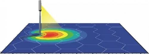
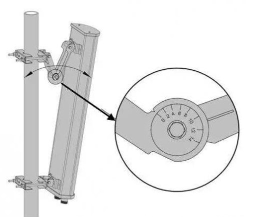
This introduces the concept of antenna downtilt.
All antennas have a knob with an angle scale on their mounting bracket, and by twisting the knob to control the mechanical movement of the bracket, the downward tilt angle can be adjusted. So, adjusting the down tilt in this way is also called mechanical down tilt.
However, this way has two obvious disadvantages.
The first is trouble. In order to do network optimization to adjust the angle, you need engineers to climb the tower on the station, the actual effect of what is not good enough to say, it is inconvenient, high cost.
The second is that the mechanical tilt adjustment is too simple and rough, and the amplitude of the antenna vertical component and horizontal component is unchanged, so it will lead to the coverage direction map is forced to be flattened, resulting in distortion.
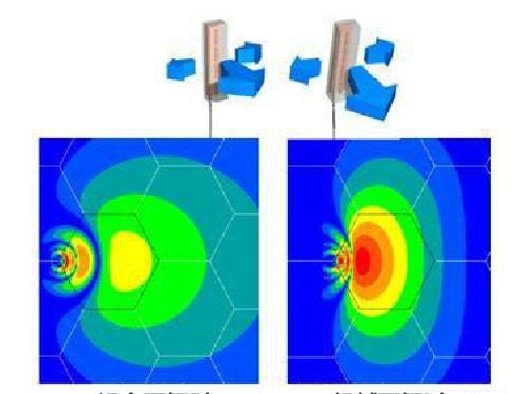
After so much effort, the coverage before and after the adjustment is completely changed, it is difficult to achieve the desired effect, but also due to the upward curvature of the rear petal leads to other base station interference also increased, so the mechanical tilt angle can only be adjusted in small increments.
So, is there a better way?
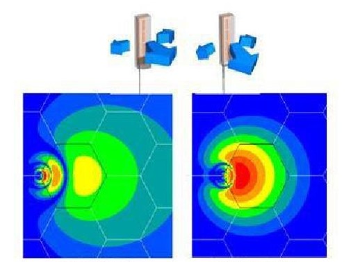
There is really a way, is to use electronic tilt. The principle of electronic downtilt is to change the phase of the common line array antenna oscillator, change the amplitude of the vertical component and the horizontal component size, change the synthesized component field strength, so that the vertical direction of the antenna figure downtilt.
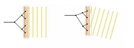
That is to say, electronic down tilt does not really need to let the antenna tilt, only need engineers in front of the computer, point and click the mouse, with the software adjustment can be. Moreover, the electronic tilt will not cause the distortion of the radiation direction map.
The simplicity and convenience of electronic tilt does not come out of nowhere, but through the joint efforts of the industry to realize.
In 2001, several antenna manufacturers get together, set up a called AISG ( Antenna Interface Standards Group ) organization, want to standardize the interface of the ESC antenna.

Until now, there have been two versions of the agreement: AISG 1.0 and AISG 2.0.
With these two protocols, even if the antenna and the base station are produced by different manufacturers, as long as they all follow the same AISG protocol, they can pass the antenna tilt control information to each other, and realize the remote adjustment of the tilt angle.
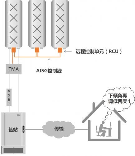
With the backward evolution of AISG protocol, not only the vertical tilt angle can be adjusted remotely, even the horizontal azimuth angle, and the width and gain of the main flap can be adjusted remotely.
Moreover, due to the increasing number of wireless bands of each operator, coupled with the dramatic increase in the number of antenna ports required by 4G's MIMO and other technologies, the antenna is also gradually evolving from a single-frequency dual-port to multi-frequency multi-port.
The principle of antenna seems simple, but the pursuit of performance excellence has no end. This article to this point, is only a qualitative description of the basic knowledge of the base station, as for the deeper mystery inside, how to better support the evolution to 5G, a wave of communications people are still up and down and seek!